



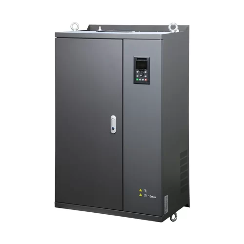
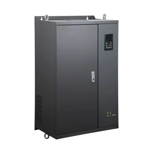
Product Overview
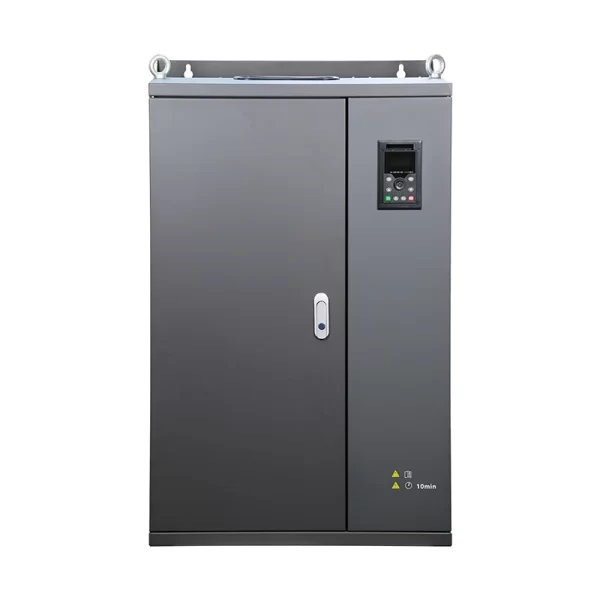
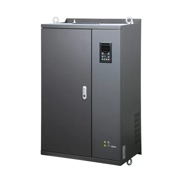
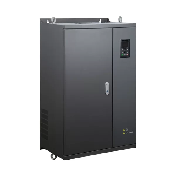
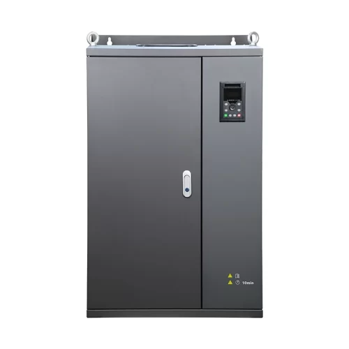
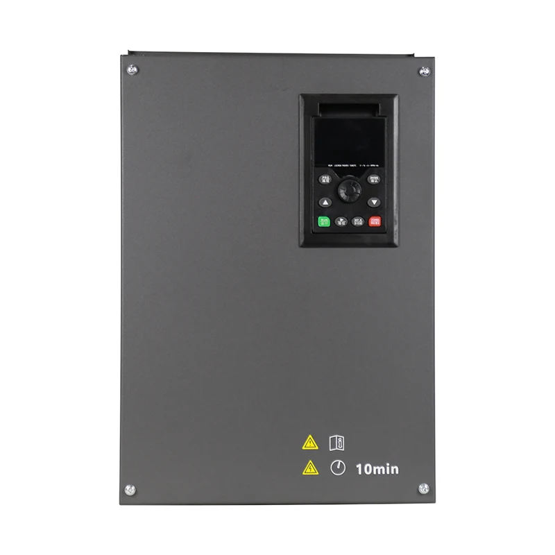
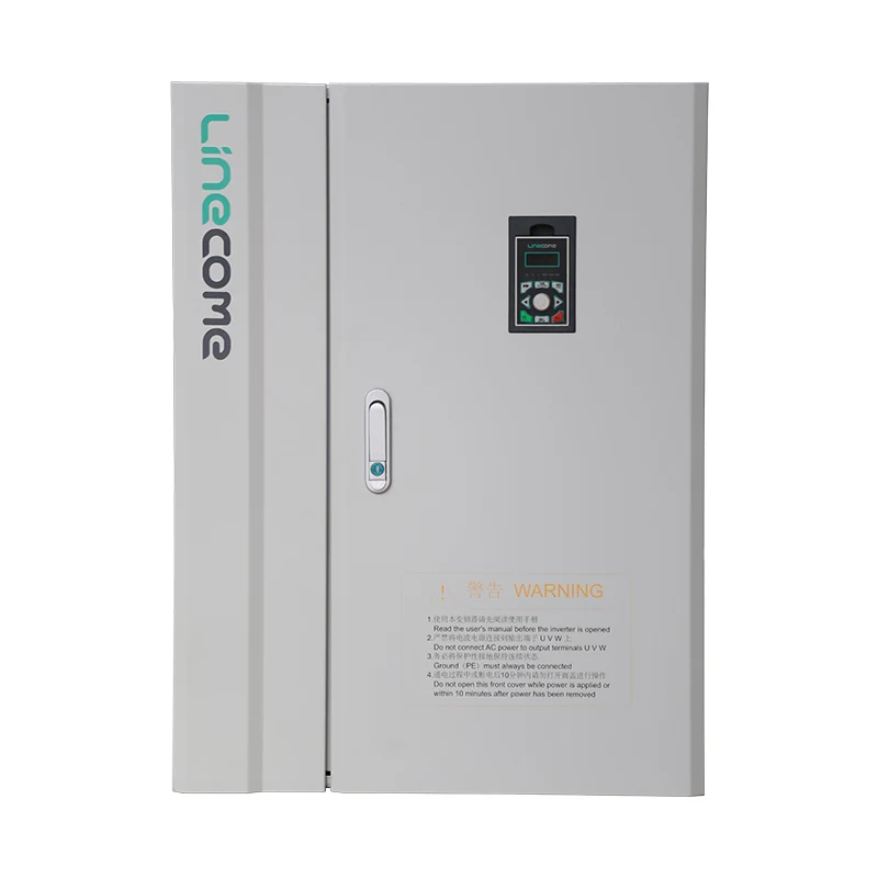
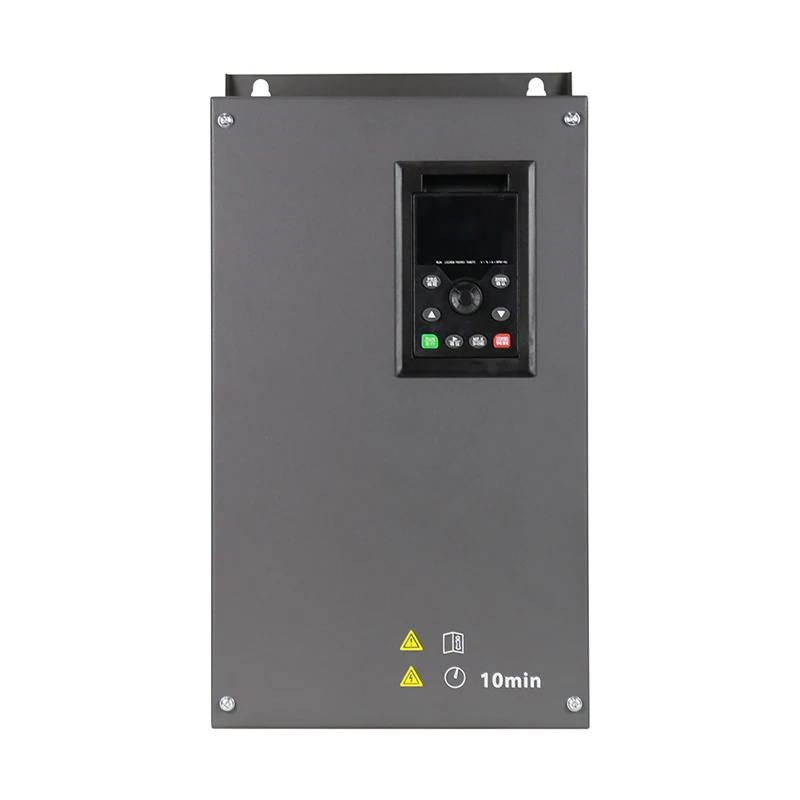
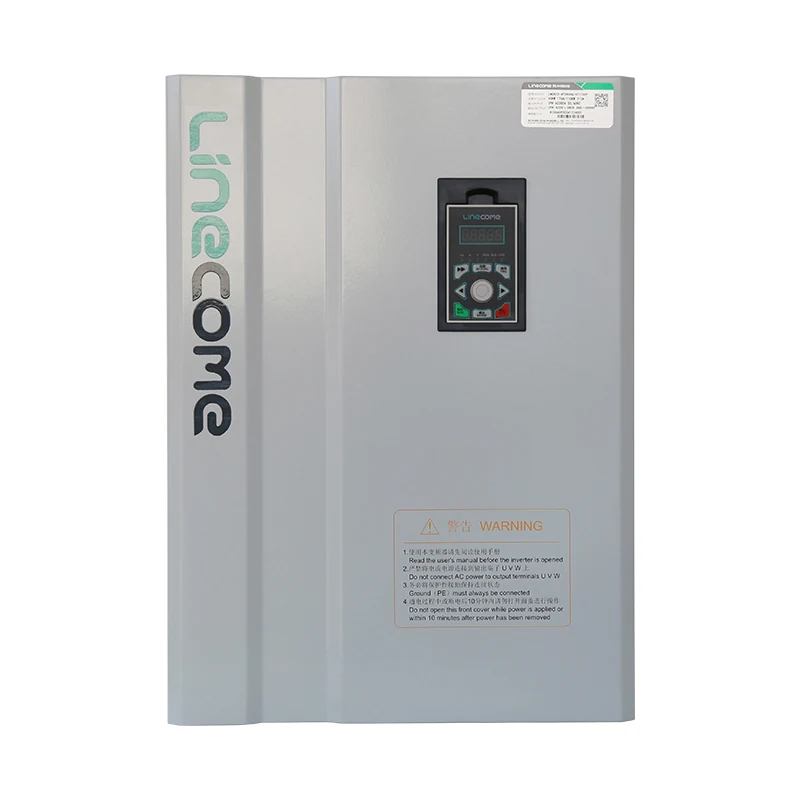
Developed for high-capacity water pumping systems, the LNC133 250–315kW series converts photovoltaic DC energy into stable three-phase AC power for large pump motors.
The advanced MPPT algorithm continuously tracks the optimum operating point of the photovoltaic array and automatically regulates pump speed based on available solar power. This helps maximize daily water output while reducing dependence on conventional grid energy.
The inverter supports RS485 communication, multi-step speed control, simple PLC, automatic voltage regulation and built-in PID. It can be integrated into centralized monitoring and automated pumping station control systems.
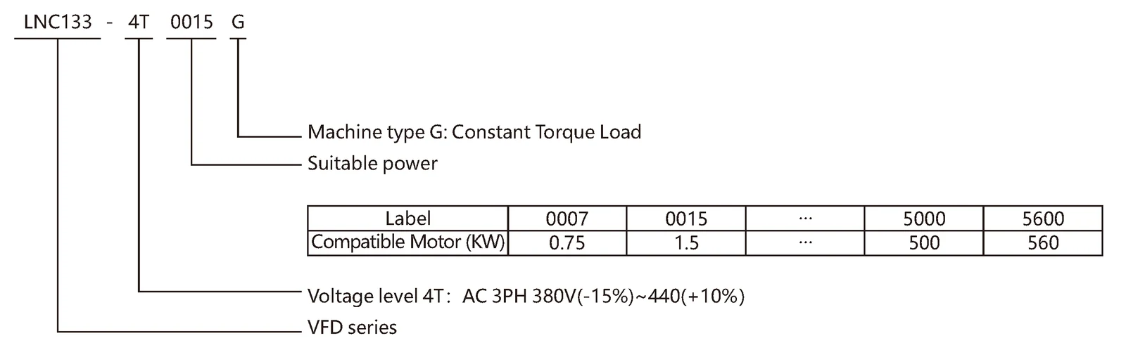
Model meaning
Product Features
- Advanced MPPT control for utility-scale photovoltaic pumping.
- 250–800V DC input voltage range.
- Three-phase 380V output for high-power pump motors.
- Open-loop vector control and V/F control.
- Standard RS485 communication.
- Dual-channel relay outputs for system interlocking.
- Built-in PID for pressure, flow and water-level control.
- Up to 16-step speed operation.
- Heavy-duty overload capability.
- Protection against overvoltage, overcurrent, undervoltage, overload, phase loss, short circuit and overheating.
- Suitable for centralized and unattended pumping stations.
Available Models
| VFD Model | Power Capacity | Input Current | Output Current | Applicable Motor |
|---|---|---|---|---|
| LNC133-4T2500G | 355kVA | 468A | 465A | 250kW |
| LNC133-4T2800G | 396kVA | 525A | 520A | 280kW |
| LNC133-4T3150G | 445kVA | 590A | 585A | 315kW |
Installation Dimensions
- Overall dimensions: 983 × 1353 × 650mm
- Overall height with base: 1392mm
- Mounting dimensions: 377 × 420 × 1030mm
- Installation hole diameter: M10
Typical Applications
- Large photovoltaic pumping stations
- Regional agricultural irrigation
- Municipal water supply projects
- Industrial water transfer
- Reservoir and river pumping
- High-flow and high-head pumping systems
- Large-scale desert and ecological restoration
Technical specifications
| Item | Specification | |
|---|---|---|
| Control characteristics | Output frequency | 0-300Hz |
| Carrier frequency | 0.5kHz ~ 15kHz, carrier frequency can be automatically adjusted according to load characteristics | |
| Frequency resolution | 0.01Hz | |
| Control mode | Open – loop vector control (SVC) V/F control |
|
| Starting torque | 0.5Hz/180%(SVC) | |
| Speed regulation range | 1:100 ( SVC ) | |
| Speed stabilization accuracy | ±0.5% ( SVC ) | |
| Torque control accuracy | ±5%(SVC) | |
| Overload capacity | G Model: 150% rated output current for 60 seconds; 180% rated current for 3 seconds | |
| Torque boost | Automatic torque boost; manual torque boost: 0.1%~30.0% | |
| V/F curve | Three modes: Linear type; Multi-point type; V/F curve | |
| Acceleration and deceleration curve | Linear or S – curve acceleration and deceleration modes; four acceleration and deceleration times; acceleration and deceleration time range 0.1~3200.0s |
|
| DC braking | DC braking frequency: 0.00Hz ~ maximum frequency. Braking time: 0.0s~32.0s, braking action current value: 0.0% ~ 100.0% | |
| Simple PLC, multi-step speed operation | Up to 16 – step speed operation can be achieved through the built – in PLC or control terminals | |
| Built – in PID | It can easily realize the process – control closed – loop control system | |
| Automatic voltage regulation (AVR) | When the grid voltage changes, it can automatically maintain a constant output voltage | |
| Overvoltage, overcurrent & stall control | Automatically limit current and voltage during operation to prevent frequent tripping caused by overcurrent and overvoltage | |
| Fast current – limiting function |
Minimize over – current faults to the greatest extent and protect the normal operation of the frequency converter | |
| Operating characteristics | Operating command channel | Three channels: given by the operation panel, given by the control terminals, given by the serial communication port. It can be switched in various ways |
| Frequency source | Main frequency sources: digital setting, analog voltage setting, analog current setting, RS485 communication setting, multi-speed segments, PID and simple PLC, switchable via multiple methods | |
| Auxiliary frequency source | Ten auxiliary frequency sources. It can flexibly achieve auxiliary frequency fine – tuning and frequency synthesis | |
| Input terminals | 6-channel digital input terminals; 2-channel analog input terminals; AI1: 0~10V voltage input; AI2: 0~10V voltage input or 4~20mA current input |
|
| Output terminals | 1- channel open collector FM; 2- channel relay output terminals; 2-channel analog output terminals, supporting 0~20mA current output or 0~10V voltage output |
|
| Display and keyboard operation | LED display | 5-digit parameter display |
| Key Locking and Function Selection |
Realize partial or full key locking and define the scope of functions of partial keys to prevent misoperation | |
| Protection characteristics | Protection function | Motor short-circuit detection upon power-on, output phase loss protection, overcurrent protection, overvoltage protection, undervoltage protection, overheating protection, overload protection, etc. |
| Environment | Application place | Indoors, not directly exposed to sunlight, free from dust, corrosive gases, flammable gases, oil mist, water vapor, dripping water or salt, etc |
| Altitude | Derating is required when the altitude exceeds 1000 meters, with a 10% derating for every additional 1000 meters. |
|
| Ambient humidity | – 10℃ ~ + 40℃ (When the ambient temperature is between 40℃ ~ 50℃, derating operation is required) | |
| Humidity | Less than 95%RH, without water droplet condensation | |
| Vibration | Less than 5.9m/s² (0.6g) | |
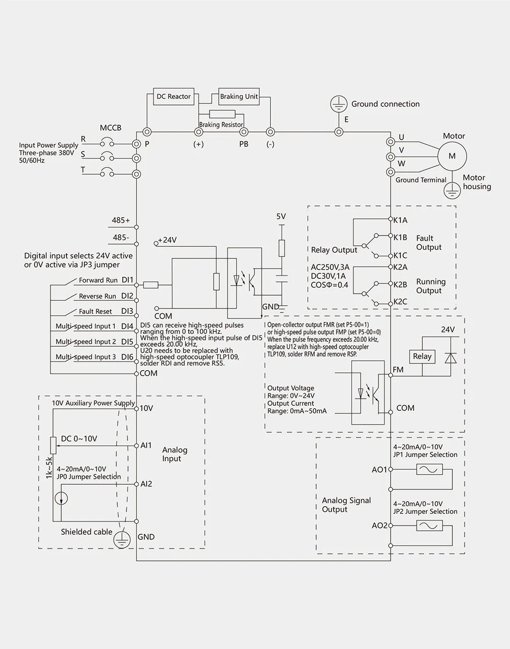
Basic wiring diagram
Installation dimensions of the keyboard base
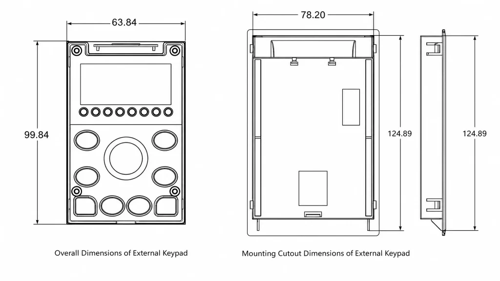
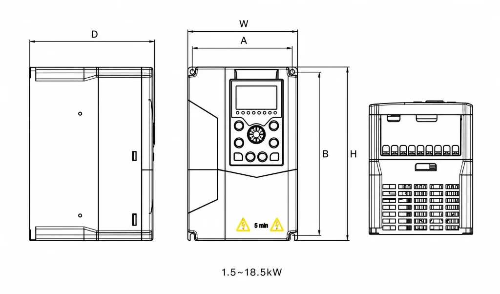
Diagrams of the overall dimensions and installation dimensions of the plastic structure
Diagrams of the overall dimensions and installation dimensions of the sheet metal structure
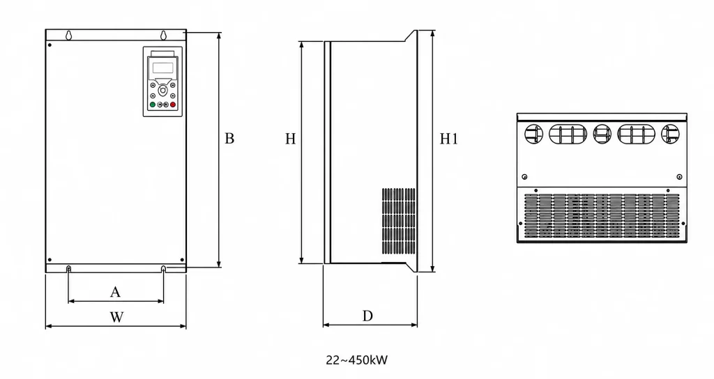
| Machine type | Overall dimensions | Installation dimensions | Installation hole diameter | ||||
|---|---|---|---|---|---|---|---|
| kW | H(mm) | H1(mm) | W(mm) | D(mm) | A(mm) | B(mm) | mm |
| 0.75-5.5 | 200 | / | 130 | 155.5 | 119.5 | 189 | M4 |
| 7.5-11 | 245 | / | 140 | 160.2 | 129 | 239 | M5 |
| 15-18.5 | 279 | / | 180 | 162.5 | 165.5 | 268 | M5 |
| 22-30 | 385 | 430 | 230 | 225 | 184 | 410 | M6 |
| 37-45 | 382 | 430 | 270 | 225 | 222 | 410 | M6 |
| 55-75 | 534 | 594 | 310 | 265 | 200 | 570 | M8 |
| 90-110 | 643 | 653 | 326 | 292 | 200 | 635 | M8 |
| 132-160 | 760 | 769 | 450 | 335 | 300 | 751 | M8 |
| 185-200 | 880 1250(with base) |
930 1275(with base) |
579 | 380 | 449 | 903 | M8 |
| 220-315 | 983 1353(with base) |
1060 1392(with base) |
650 | 377 | 420 | 1030 | M10 |
| 355-450 | 1203 1653(with base) |
1358 1731(with base) |
800 | 400 | 520 | 1300 | M14 |


Reviews
There are no reviews yet.