



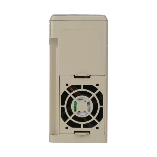
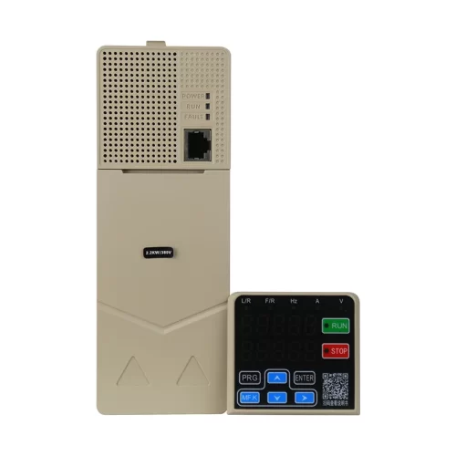
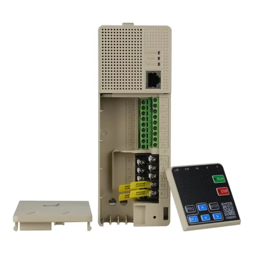
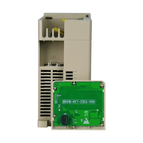
Overview
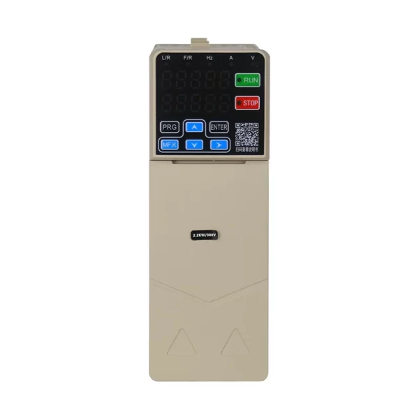
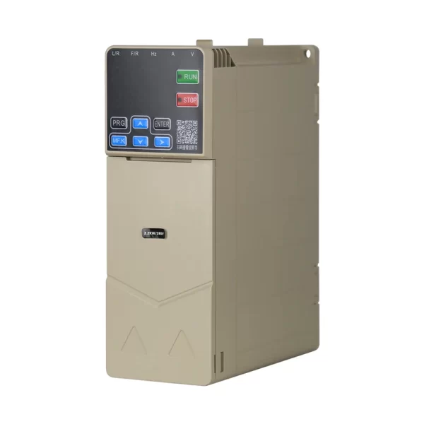
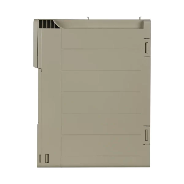
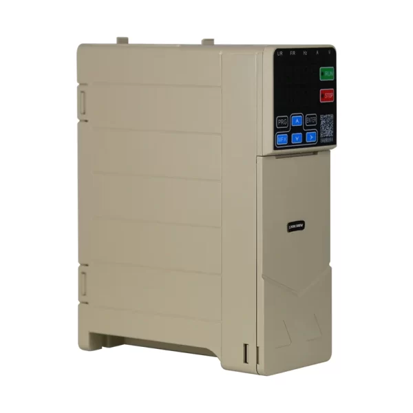
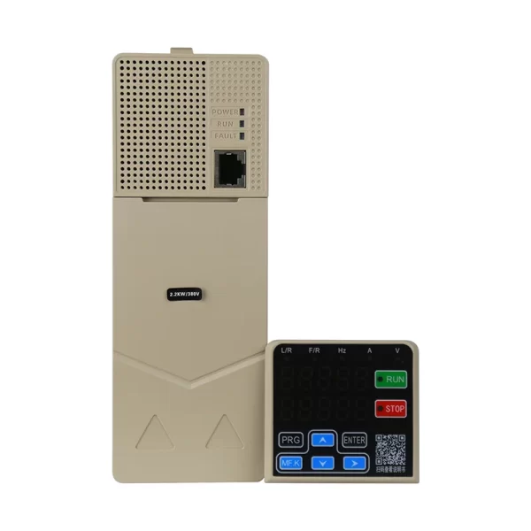
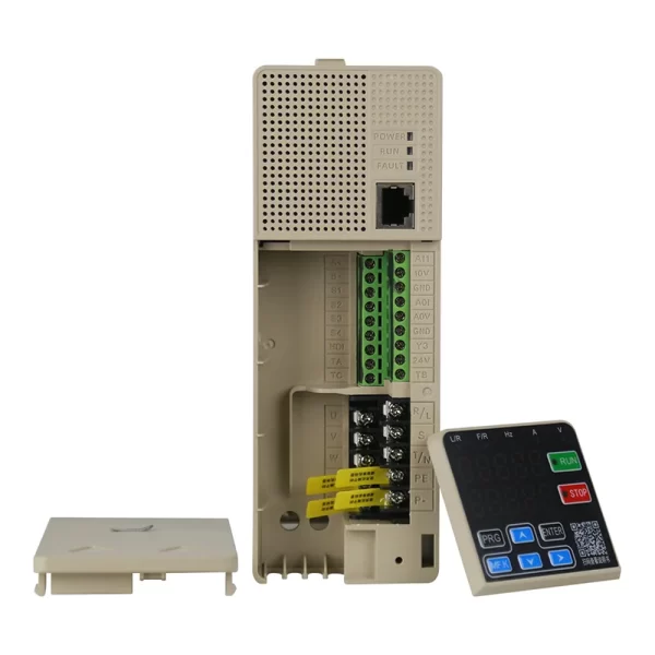
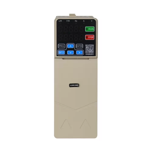
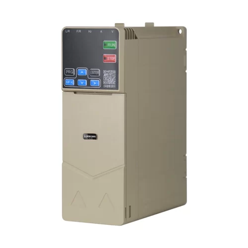
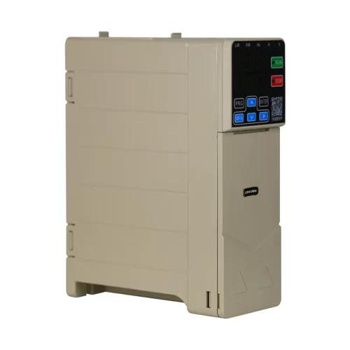
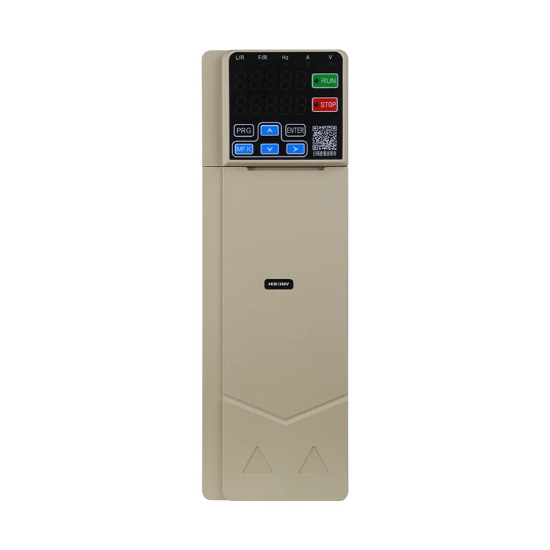
The LNC610 series VFD is developed on a brand-new hardware and software platform. It is a general-purpose vector inverter featuring high power density, comprehensive protection functions and complete application functions, designed to better meet the market demands of machine tools, printing, textile, chemical fiber, stone, engraving and other mechanical equipment. It supports the standard Modbus communication protocol and synchronous motors. The 610 series is not equipped with a braking unit by default. Please note to add the braking unit when placing an order if braking function is required.
Model meaning
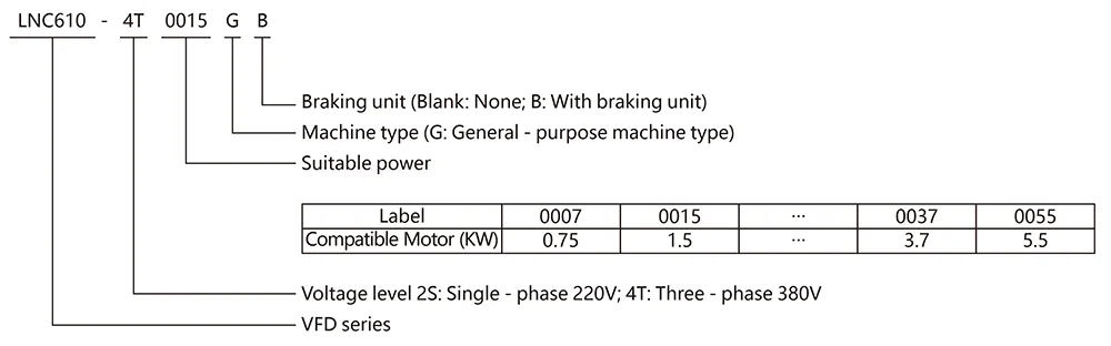
Current Parameter
| VFD model | Power capacity (kVA) | Input current (A) | Output current (A) | Applicable motor (KW) |
| Single-phase power supply: 220V ±10%, 50/60Hz, actual permissible range: AC 198V – 242V | ||||
| LNC610-2S0007G | 2.0 | 12.5 | 5.0 | 0.75 |
| LNC610-2S0015G | 3.0 | 19.0 | 8.0 | 1.5 |
| LNC610-2S0022G | 4.3 | 24.0 | 11.0 | 2.2 |
| Three-phase power supply: 380V ±15%, 50/60Hz, actual permissible range: AC 323V – 437V | ||||
| LNC610-4T0007G | 1.5 | 3.4 | 2.5 | 0.75 |
| LNC610-4T0015G | 3.0 | 5.0 | 4.2 | 1.5 |
| LNC610-4T0022G | 4.0 | 5.8 | 6.0 | 2.2 |
| LNC610-4T0037G | 5.9 | 10.5 | 9.5 | 3.7 |
| LNC610-4T0055G | 8.9 | 14.6 | 13.0 | 5.5 |
Technical specifications
| Item | Specification | |
|
Basic functions |
Output frequency | 0-500Hz |
| Carrier frequency | 0.8kHz ~ 12kHz, the carrier frequency can be automatically adjusted according to the load characteristics | |
| Frequency resolution | 0.01Hz | |
| Control mode | V/F control, open-loop vector control (SVC) | |
| Torque characteristics | With torque compensation and slip compensation, starting torque: G – type machine 0.5Hz/150% | |
| Torque boost | Automatic torque boost; Manual torque boost 0.1% ~ 30.0% | |
| Overload capacity | G – type machine: 150% of rated output current for 60S | |
| Speed regulation range | 1:100 | |
| Speed stability accuracy | ±1% | |
| Automatic voltage regulation (AVR) | When the grid voltage changes, it can automatically maintain a constant output voltage | |
| Over – voltage and
over – current stall control |
Automatically limits the current and voltage during operation to prevent frequent over – current and over – voltage tripping | |
| Fast current – limiting function | Minimizes over – current faults to protect the normal operation of the frequency converter | |
| V/F curve | Four modes: linear type; multi – point type; complete V/f separation; incomplete V/f separation | |
| Acceleration and deceleration curves | Linear or S – curve acceleration and deceleration modes; four acceleration and deceleration times; acceleration and deceleration time range: 0.1 ~ 6500.0s | |
| DC braking | DC braking frequency: 0.00Hz ~ maximum frequency, braking time: 0.0s ~ 36.0s, braking action current value: 0.0% ~ 100.0% | |
| Jog control | Jog frequency range: 0.00Hz ~ 50Hz; jog acceleration and deceleration time: 0.0s ~ 6500.0s | |
| Simple PLC, multi – speed operation | Up to 16 – speed operation can be achieved through the built – in PLC or control terminals | |
| Built – in PID | It can easily implement a process – control closed – loop control system | |
|
Operating characteristics |
Operating command channel | Three channels: given by the operation panel, given by the control terminals, given by the serial communication port. It can be switched in various ways |
| Frequency source | Ten frequency sources: given by operation panel, given by analog voltage, given by analog current, given by RS485 communication, multi – speed, PID, simple PLC, which can be switched in various ways | |
| Auxiliary frequency source | Ten auxiliary frequency sources. It can flexibly achieve auxiliary frequency fine – tuning and frequency synthesis | |
| Input terminals | 5 digital input terminals. Among them, S5 can also serve as a high-speed pulse input channel with a maximum input frequency of 50kHz. One analog input AI1, which can switch between voltage and current via parameter P4-37. | |
| Output terminals | One relay output terminal and one analog output terminal AO1.One open-collector output (can also be used as high-speed pulse output), switchable via parameter P5-00, with a maximum frequency up to 50kHz. | |
| Display and keyboard |
Dual LED Display |
It can perform forward rotation, reverse rotation, reset, stop, jog operation, as well as parameter setting and display.Upper LED display: 5-digit main LED display, which can show the set frequency, output frequency, various monitoring data, alarm codes, etc.
Lower LED display: 5-digit auxiliary LED display, which can show the set frequency, output frequency and various monitoring data. The specific display content shall be set via parameters P7-17 and P7-18. |
| Protection characteristics | Protection function | Motor short – circuit detection upon power – on, output phase – loss protection, over – current protection, over – voltage protection, under – voltage protection, over – heat protection, overload protection, etc |
|
Environment |
Application place | Indoors, not directly exposed to sunlight, free from dust, corrosive gases, flammable gases, oil mist, water vapor, dripping water or salt, etc |
| Altitude | Less than 1000m | |
| Ambient humidity | – 10℃ ~ + 40℃ (When the ambient temperature is between 40℃ ~ 50℃, derating operation is required) | |
| Humidity | Less than 95%RH, without water droplet condensation | |
| Vibration | Less than 5.9m/s² (0.6g) | |
| Storage temperature | – 20℃ ~ + 60℃ | |
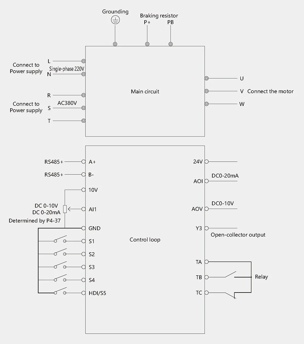
Basic wiring diagram
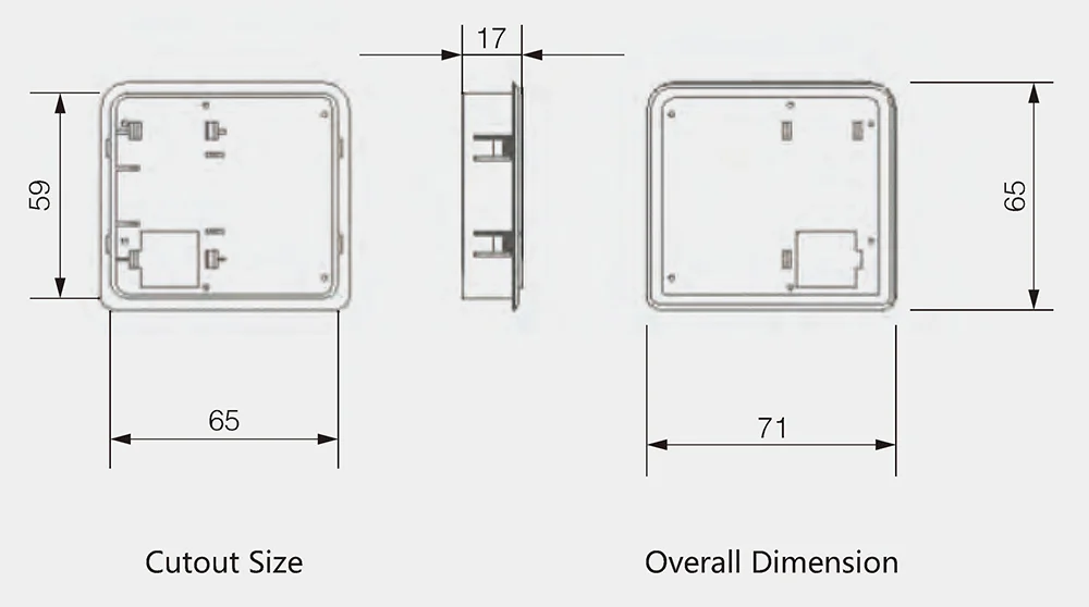
Installation dimensions of the keyboard base
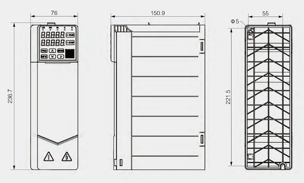
Overall installation dimensions
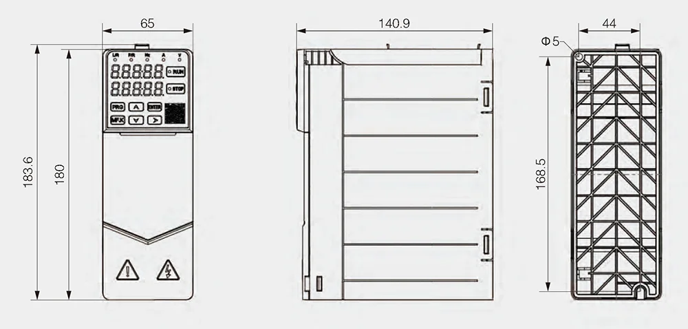
Overall Dimensions and Mounting Dimensions for 0.75-1.5kW 220V, 0.75-2.2kW 380V
Overall Dimensions and Mounting Dimensions for 2.2kW 220V, 3.7-5.5kW 380V
Details


Reviews
There are no reviews yet.