




Circuit breaker temperature derating means checking how the actual installation temperature changes the device’s usable current or trip behavior, using information for the exact breaker and assembly. The temperature near the installed device can differ from the room temperature. Do not respond to a hot enclosure or an unwanted trip by simply increasing the breaker rating. First establish the load, local temperature, trip-unit type, conductor limits and approved installation conditions, then review the protection design as a whole.
This guide focuses on temperature and enclosure evidence for panel buyers and maintenance teams. It does not provide a universal correction factor or authorize a change to a protective setting. Short-circuit capability, coordination and cable protection remain separate acceptance requirements.
Identify the breaker and its published conditions
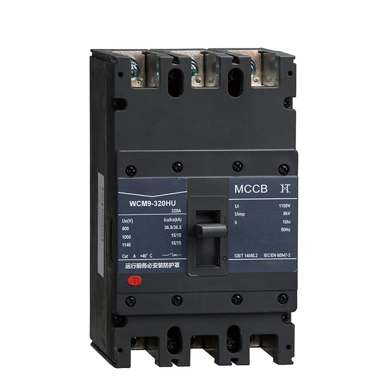
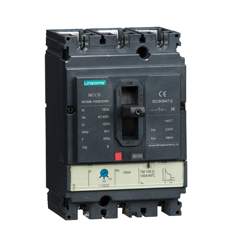
Record the full model, frame, rated current, trip unit, settings, number of poles and relevant accessory references. Similar-looking breakers can use different sensing arrangements and different published limits. A current value on the front of a device is not the complete application specification.
The WCM8 moulded case circuit breaker is one relevant LINECOME product family. Its page lists environmental conditions, including temperature limits. Use the current product document and supplier confirmation for the exact ordered device. A catalog operating range is not a temperature-versus-current curve and should not be converted into an invented derating percentage.
Ask where the published ambient temperature applies and under what mounting and loading conditions it was established. If the device sits within another enclosure, clarify the air temperature surrounding the breaker rather than using only an outdoor weather reading. Also distinguish storage conditions from permitted energized operation.
Separate ambient temperature, temperature rise and trip behavior
Ambient temperature describes the surrounding environment at the defined reference location. Temperature rise describes how much a component warms above the relevant ambient under stated conditions. A measured surface temperature is neither automatically the surrounding air temperature nor a direct reading of the internal trip element.
The IET discussion of grouped circuit breakers explains why neighboring loaded devices and an enclosure affect thermal conditions. Its consumer-unit examples should not be copied as rating factors for an industrial MCCB. The useful principle is to evaluate the actual installation and obtain the appropriate manufacturer information.
Thermal, thermal-magnetic and electronic trip arrangements must not be treated as interchangeable. Electronic sensing may behave differently from an uncompensated thermal element, but that does not remove thermal limits on terminals, conductors or the complete breaker. Record which limits relate to trip behavior and which relate to continuous operation.
Measure the environment that the device actually sees
Agree a measurement plan with competent personnel. Record sensor location, loading, enclosure condition, operating period and the surrounding room conditions. A reading taken immediately after startup may not represent a long production run, and a test with the cabinet door open may not represent normal service.
Plan measurements without exposing people to energized parts or defeating enclosure protection. Use the site’s approved safe method and equipment. The HSE guidance for work on electrical equipment is the safety reference for this discussion; this article does not instruct readers to probe an energized panel.
Compare representative operating states. Adjacent circuits may be lightly loaded during inspection and heavily loaded during normal production. Heaters, drives, transformers and external solar exposure may also change the environment. A useful record states what was operating rather than presenting a single temperature with no context.
Inspect causes of excess heat before changing the rating
Review the load history and whether the installed duty matches the approved design. Record each relevant phase current using an approved measurement process and compare the result with the protective settings and equipment documents. Repeated operation near a limit is different from a brief starting event or an abnormal fault.
Check ventilation, filters and enclosure clearances against the assembly design. A blocked air path or failed cooling component may change the temperature around otherwise correctly selected devices. The separate control cabinet cooling fan maintenance guide helps organize that inspection without turning a breaker setting into a substitute for cooling maintenance.
Connection condition also requires attention. Loose, damaged or incorrectly prepared terminations can create localized heating. Inspection, tightening and replacement must follow safe isolation and the specific terminal instructions. Do not apply a generic torque value, tighten live connections or assume a thermal image alone identifies the root cause.
Build a device-specific decision table
The table below is a procurement and investigation aid. It uses the installation principle described by the IET, not the article’s example factors. The necessary numerical limits come from the exact device and assembly documentation.
| Evidence | What it helps distinguish | Required next step |
|---|---|---|
| Exact breaker and trip-unit reference | Different products within a similar enclosure | Obtain the matching application documents |
| Local ambient record | Room conditions versus device surroundings | Compare with the defined reference conditions |
| Load and duty history | Continuous loading versus starting or fault events | Review against protection and equipment limits |
| Adjacent loaded circuits | Mutual heating and assembly effects | Obtain assembly-specific guidance |
| Terminal condition and conductor data | Local connection heating versus general ambient | Inspect using approved isolation and preparation methods |
| Cooling and enclosure condition | Changed installation environment | Restore or redesign the approved thermal arrangement |
| Trip indication and event record | Overload, short circuit or another protection function | Diagnose the indicated function before changing settings |
| Supplier correction information | Actual permitted current and installation boundaries | Recheck the complete protection design |
If information is unavailable, keep that item open. A quotation stating “suitable for hot climates” is not a substitute for a documented operating limit under the intended enclosure conditions.
Understand a derating calculation before applying it
Some manufacturer documents express temperature correction as a factor applied to a reference current. In that particular convention, an allowable current can be written as reference current multiplied by the applicable factor. Other tables directly state the permissible current or show how a trip threshold changes. Read the table definition before multiplying anything.
For an arithmetic illustration only, suppose a hypothetical document defines a reference current of 100 A and a correction factor of 0.90 for a stated installation. The calculation is 100 A × 0.90 = 90 A. These are invented teaching inputs, not WCM8 data, a recommended breaker size or evidence that any LINECOME device may be used at an unspecified temperature.
The result would still need to be checked against the actual load, conductor capacity, equipment ratings, starting requirements and required protection. Combining several factors may also require a manufacturer-specific method; do not multiply unrelated ambient, grouping and enclosure factors unless the applicable instructions permit that approach.
Do not confuse a larger frame with an approved solution
A larger frame, a different trip unit or a different enclosure arrangement may be part of an engineered redesign. None should be selected solely because it stops a nuisance trip. The revised device must still protect the cable and downstream equipment and meet fault-level and coordination requirements.
Use the separate motor control panel breaker coordination checklist to collect those protection details. Temperature assessment adds an environmental condition to that review; it does not replace it. A device with adequate continuous-current capability can still be unsuitable for the available fault current or required protective behavior.
Any proposed change should identify the previous design, the new selection and the evidence supporting it. Preserve settings before adjustment, record the approved revision and state the checks needed before returning the panel to service. A successful short run is not proof of acceptable long-term thermal operation.
Include the complete assembly in the enquiry
For a cabinet order, supply the room conditions, expected duty, enclosure arrangement and adjacent heat sources. Identify whether the panel will operate with doors closed, in a restricted room, outdoors or near another hot process. Give the supplier the actual installation assumptions rather than a broad description of the country or climate.
A PLC control cabinet overview explains the range of equipment that may share an enclosure. The thermal review should cover that complete assembly, not just the main breaker. Busbars, terminals, power supplies and cables have limits that remain relevant even when the breaker itself operates normally.
Ask the supplier to state exclusions and assumptions. If a quoted enclosure relies on filtered ventilation, maintenance access and filter condition become part of the operating arrangement. If a different cooling method is required, assess condensation, ingress protection and environmental compatibility as well as heat removal.
Verify the correction under representative conditions
After an approved repair or design change, repeat the relevant inspection and operating checks with the documented load and enclosure configuration. Compare the measured conditions with the acceptance limits agreed before the work. Record unresolved differences instead of closing the issue because no trip occurred during the visit.
Keep the evidence with the panel documents: breaker reference, settings, supplier guidance, temperature record, load state, corrective action and final result. Where seasonal conditions were not reproduced, state that limit and identify any follow-up observation required. This makes the conclusion useful without overstating what the test established.
Watch how a circuit breaker operates
The following RealPars video explains basic breaker operation. It supports the distinction between normal current and protective operation, but it does not provide temperature correction factors or authorize a rating change for the illustrated products.
Video by RealPars. Watch Circuit Breaker Explained | Working Principle on YouTube.
Frequently asked questions
Is room temperature enough to select a circuit breaker?
Not necessarily. Check the reference location in the product documents and the environment around the installed device. Internal heat sources, neighboring circuits and the enclosure can make local conditions different from the room reading.
Can the same temperature factor be used for every breaker?
No. Use information for the exact breaker, trip unit and installation conditions. A factor from another product or a consumer-unit example is not evidence for an industrial MCCB. The meaning of the factor must also be checked before calculation.
Should a breaker be upsized when it trips in hot weather?
Only after an approved protection review identifies that change as suitable. First investigate load, local heat, cooling, connections and the indicated trip function. Increasing a rating without checking cable and equipment protection can create a different hazard.


