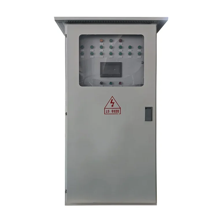
Solar pump inverter MPPT adjusts the photovoltaic array’s operating point to extract useful available electrical power as sunlight and module conditions change. It does not create extra sunlight, guarantee a fixed water flow or replace pump protection. In a pumping system, the controller must reconcile available solar power with the motor, pump, water source and demand. A pressure command may request more output than the array can support, so the approved control sequence must define what happens when power becomes insufficient.
The commissioning objective is therefore broader than seeing an MPPT indication on the display. Verify that the array remains within the inverter’s electrical limits, the pump produces useful water at the actual head, and transitions through changing sunlight follow the agreed operating sequence.
For the wider motor-control context, the VFD operating-principle guide explains conversion from electrical input to controlled motor output. Solar tracking adds a source-power constraint to that conversion.
Separate three different control questions
MPPT concerns the electrical power available from the solar array. Motor control concerns the voltage, frequency and current needed by the connected motor. Hydraulic control concerns what the water system needs, such as filling a storage tank or maintaining pressure. These tasks interact, but they answer different questions and should not be collapsed into a single “automatic” function.
For example, a pressure controller can demand higher speed when pressure falls. Under strong sunlight, the array may support that request. Under cloud cover, the same command may exceed the available power. The selected inverter’s control logic must arbitrate these conditions. The engineer should confirm whether pressure control, solar tracking and low-power handling can operate together in the intended mode.
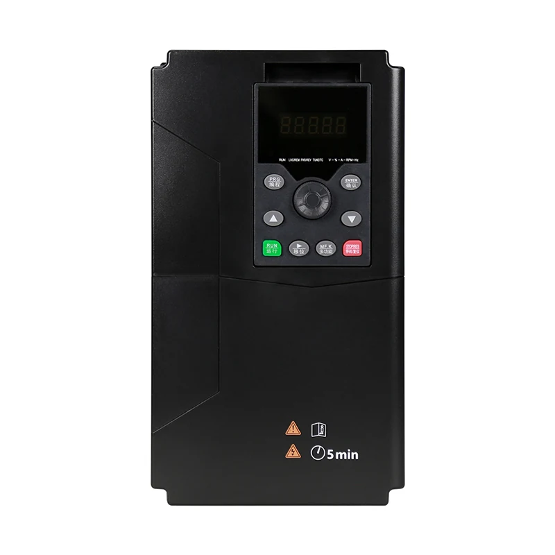
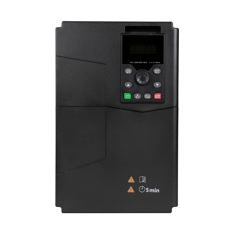
LINECOME’s LNC133 solar water pump inverter product page describes MPPT and pump-control applications. Use it to identify the relevant product family, then obtain the exact model documentation for input limits, motor compatibility and command priority. The photographs in this article establish product appearance only; they do not demonstrate an installed array, a water-output test or an approved parameter combination.
Understand the array operating point
A photovoltaic array supplies different combinations of voltage and current depending on its operating conditions and connected load. Electrical power at an observed operating point is voltage multiplied by current. MPPT seeks a useful maximum-power operating point within the controller’s supported range. Reading voltage alone does not establish how much power is being delivered.
As a purely arithmetic illustration, an observed 300 V and 8 A corresponds to 2,400 W of DC electrical input at that measurement point. Another observation of 320 V and 6 A corresponds to 1,920 W. The second voltage is higher while the power is lower. These are hypothetical readings, not LNC133 input ratings, an MPPT test curve or evidence that either operating point is optimal.
Actual maximum-power tracking performance requires suitable measurement and a valid comparison under known conditions. Rapid changes in irradiance complicate comparisons taken at different times. Ask the supplier how its MPPT performance is specified and tested; do not turn two display screenshots from different weather conditions into an efficiency claim.
Check the electrical envelope before tracking performance
MPPT operates within hardware limits. Confirm the array design against the exact inverter’s permissible DC voltage, current, polarity and supported operating range. The review should include temperature-related string-voltage conditions and applicable array-design rules. The final series and parallel arrangement belongs in an approved electrical design, rather than being selected from the pump’s kilowatt label alone.
The World Bank’s Solar Pumping: The Basics describes the need to match solar modules, power conditioning, motor and pump. It also explains why array quality and the actual pump performance curve matter. Its general guidance does not supply input ratings or string counts for a LINECOME inverter.
Record module identification, string arrangement, protective equipment, cable design and the inverter model before energizing. Qualified personnel should follow the installation and isolation procedures for the complete PV system. A stopped motor does not mean the solar DC circuits are de-energized. Test planning must account for the source remaining energized whenever illuminated.
Judge performance at the actual water head
Useful pumping requires the pump to overcome the system’s head and losses. A rotating motor can consume energy while delivering little or no useful water at the destination. Under reduced sunlight, a centrifugal pump may slow until it cannot overcome the required head. A frequency display alone is therefore not a water-output acceptance test.
Document the source water level, delivery elevation, pipe arrangement, valve condition and measured flow or accumulated water volume. Compare the observed duty with the approved pump curve and motor operating limits. Where water levels change during the day or season, include those conditions in the design review. A noon demonstration with a shallow water level may not represent the difficult operating period.
The World Bank’s solar pumping design overview identifies water demand, storage, head, array location and solar resource as design inputs. A practical acceptance plan should connect those inputs to the customer’s required water service rather than promising a daily volume from inverter power alone.
Distinguish MPPT, PID and protective functions
Use the following qualitative checklist to agree on the control responsibilities. It is a review framework based on solar pumping system principles and the selected product documentation; it is not a claim that all listed functions are standard on every inverter.
| Function or condition | Main question | Evidence needed at acceptance |
|---|---|---|
| MPPT | Is the array operating point being managed for available power? | Mode selection and approved electrical observations |
| Pressure PID | Is the pressure demand met when power and hydraulics permit? | Sensor range, command priority and pressure response |
| Low solar power | What happens when useful pumping cannot continue? | Defined slow-down or stop sequence and restart conditions |
| Dry-run protection | Is the water source available to the pump? | Verified detection method and separate trip test |
| Tank full | Should pumping stop despite abundant sunlight? | Level input, stop behavior and release condition |
| Hybrid source operation | Which source may supply the drive? | Approved power architecture and interlocking documentation |
Dry-run protection remains a separate subject. A low-power observation does not uniquely establish an empty source. Use the solar pump dry-run protection guide to review that function independently. Do not disable it to keep an MPPT demonstration running.
Observe low-sun transitions without forcing a fault
Agree on a test method with the supplier and site engineer. Prefer planned observation during suitable natural conditions or an approved test facility. Do not improvise array switching, connector disconnection or deliberate module shading while energized. Such actions can create hazards or misleading electrical conditions and may violate the equipment instructions.
The record should identify the initiating condition and distinguish a controlled low-power stop from a protective trip. Record the operating mode, available DC observations, output frequency, motor current, water flow and relevant status messages on a common timeline. Include the reason pumping resumed. A restart caused by an operator reset is different from the controller’s documented automatic low-sun recovery.
Check for repeated cycling around the usable-power threshold. The appropriate delay or hysteresis depends on the inverter, motor, pump and water system. There is no universal timer that can be recommended from the product photograph. The accepted configuration should avoid unnecessary starts while providing the required service under the assessed conditions.
Coordinate pressure demand and power availability
A constant-pressure system needs a defined response when solar input cannot meet demand. The approved sequence may allow reduced service, stop under specified conditions, use stored water or draw from an engineered alternative source. Which response is acceptable depends on the project. MPPT should not be described as a guarantee that pressure will remain constant through cloud cover.
If a pressure sensor is used, verify its range, units, scaling and failure response before evaluating regulation. The VFD pump PID commissioning guide addresses loop behavior; solar power availability adds another boundary to that loop. A pressure tuning change cannot compensate for an undersized array or a pump that cannot achieve the required hydraulic duty.
Tank filling can have a different objective from constant-pressure distribution. An appropriately designed storage arrangement may separate daytime pumping from later water use. Define tank-full behavior and source-water restrictions so the controller does not continue maximizing pumping when there is no legitimate demand or when abstraction must stop.
Build an acceptance record that can be compared later
Use repeatable measurement locations and clearly identify instrument units. Keep the array configuration, motor data, pump curve, parameter file and test conditions together. For daily water-volume acceptance, record the measurement period and relevant solar and hydraulic conditions. A brief flow reading should not be reported as a verified daily yield.
Separate conversion losses from unavailable sunlight, hydraulic losses and control restrictions. A low water total can arise from several causes: inadequate solar resource, excessive head, poor array condition, a closed valve, restrictive demand control or an electrical limit. Start with the system record rather than blaming MPPT from a single symptom.
For a new enquiry, provide required water volume and delivery schedule, source and destination levels, pump and motor details, array information, site environment and any alternative power source. Ask the supplier to explain the selected architecture and document the available operating modes. Request settings and wiring information for the exact delivered model, not a generic solar-drive diagram.
Further learning: where solar power comes from
The TED-Ed lesson below explains photovoltaic electricity generation and the variability of solar energy. It provides background for the available-power discussion; it does not specify MPPT parameters, pump sizing or a wiring procedure for this product.
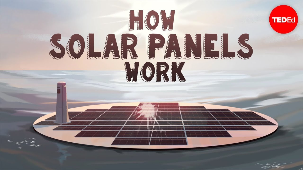
Video by TED-Ed. Watch How do solar panels work? – Richard Komp on YouTube.
Frequently asked questions
Does MPPT guarantee constant pump speed?
No. MPPT manages the photovoltaic operating point. Pump speed depends on the controller’s operating mode, available power, motor limits and hydraulic demand. Verify the selected inverter’s command priorities and low-power behavior.
Can MPPT replace dry-run protection?
No. Available solar power and source-water availability are different conditions. Specify and test the dry-run detection method separately, using the exact pump and inverter documentation and the site’s approved test procedure.
Can daily water output be calculated from inverter kilowatts alone?
No. Solar resource, array design, pumping head, pump performance, storage, demand and operating restrictions all affect delivered water. Use a system design and a documented test period rather than treating the inverter rating as a daily-yield promise.