




PLC analog input scaling converts a measured electrical signal or module data value into an engineering quantity such as pressure, level or temperature. For a linear 4–20 mA transmitter, 4 mA corresponds to the configured lower measurement limit and 20 mA to the upper limit. Correct scaling requires both limits, the actual input configuration and the module’s data format. Keep signal quality separate from the calculated value so a broken loop, invalid channel or stale reading cannot quietly appear as a believable process measurement.
This guide explains the conversion and acceptance record for a PLC cabinet. The arithmetic examples are hypothetical training cases, not LINECOME product specifications or proposed alarm settings. Confirm actual module endpoints and transmitter ranges from the approved project documents.
Define what the number represents
Begin with the transmitter’s calibrated range, including units and whether its output is linear. A pressure instrument with a wide measuring capability may be configured to transmit only part of that capability. The PLC needs the configured range, not simply the largest number printed in the catalog.
Next identify what the input module delivers to the application. It might report raw counts, a current value or a value already converted into engineering units. The same tag name can conceal different formats after a replacement module or a configuration change. Inspect the channel settings and data representation before editing the conversion formula.
The textbook treatment of current signal systems explains the live-zero relationship between current and measurement span. That relationship establishes the signal convention; the PLC manufacturer’s manual still determines the actual digital representation used by a particular module.
Use one transparent linear equation
For a linear channel, express the conversion as:
Engineering value = EU_low + (Input − Input_low) × (EU_high − EU_low) / (Input_high − Input_low).
EU_low and EU_high are the engineering values at the configured endpoints. Input_low and Input_high are the matching module values at those same endpoints. Input is the current sample in the same representation. The denominator must be nonzero, and the arithmetic must preserve fractional results where the application needs them.
If the module reports current directly in mA, Input_low is 4 and Input_high is 20 for a configured linear 4–20 mA span. If it reports counts, substitute the documented count values for those two current points. Do not insert a familiar full-scale count just because it was used on a different PLC.
As a hypothetical example, a linear transmitter spans −25 to 175 °C. At 10 mA, the fraction of electrical span is (10 − 4) / 16 = 0.375. The corresponding temperature is −25 + 0.375 × 200 = 50 °C. The negative lower limit remains part of the calculation; multiplying current by a single gain would miss it.
Check raw counts with the same endpoint method
Suppose a training module is documented to report 2,000 counts at 4 mA and 26,000 counts at 20 mA. These are deliberately hypothetical values and must not be copied into a real program. A reading of 11,000 counts represents (11,000 − 2,000) / (26,000 − 2,000) = 0.375 of span, again producing 50 °C for the example range.
Calculate expected results independently before running the program. The following table uses the same hypothetical temperature range. It is a commissioning worksheet example derived from the linear equation, not a calibration certificate or a statement of achievable accuracy.
| Injected current (mA) | Fraction of configured span | Expected temperature (°C) | Hypothetical module counts |
|---|---|---|---|
| 4 | 0 | −25 | 2,000 |
| 8 | 0.25 | 25 | 8,000 |
| 10 | 0.375 | 50 | 11,000 |
| 12 | 0.50 | 75 | 14,000 |
| 16 | 0.75 | 125 | 20,000 |
| 20 | 1 | 175 | 26,000 |
Verify both endpoints and intermediate values. Two endpoint matches can miss rounding, clipping or a separate display transformation. An intermediate point that is not exactly half span helps reveal errors that happen to cancel at the midpoint.
Decide where conversion happens
Choose a documented location for engineering conversion: module configuration or application logic, as permitted by the platform and project standard. Keep that choice visible to the next person maintaining the cabinet. An input already scaled to temperature should not pass through a second raw-count conversion.
The City of Tulsa PLC Software Standard provides one explicit project example: it assigns engineering conversion to its analog input application block rather than duplicating it at card level. This is a local software architecture, not a rule that every PLC must implement identically. Its useful lesson is to make ownership unambiguous.
Retain the unmodified module value alongside the calculated process value where the design permits. That makes troubleshooting possible without reverse-calculating a rounded HMI display. Record the channel quality information at the same time so the raw number is not mistaken for valid data during a module fault.
Keep invalid data distinct from a low process value
A live zero gives the receiving system a way to distinguish the normal low endpoint from some abnormal conditions, but it does not automatically implement a complete diagnostic strategy. Actual under-range, over-range, wire-break and device-fault behavior depends on the transmitter, module and configuration. Use those documents to define the applicable states.
Do not simply clamp every value below the configured range to the minimum engineering value before checking validity. That can turn a signal failure into an apparently ordinary empty tank or low pressure. Evaluate quality first, then apply any display limits or control restrictions required by the approved sequence.
Define what each consumer should do when data becomes invalid. An operator display, historical trend and control loop may need different responses, all documented. Holding the last good value can be useful for display continuity, but its age and invalid status must remain apparent. A stale value must not silently retain the authority of a current measurement.
Separate scaling errors from wiring and noise
A consistent offset suggests checking the low endpoint, transmitter range and any secondary conversion. A proportional error suggests checking span and units. A value that changes abruptly or intermittently needs examination of signal quality, power, wiring and the module before the gain is adjusted.
Use the existing guide to PLC analog input noise when the measured electrical signal itself is unstable. A mathematically correct scale cannot repair a poor signal, while adding a filter cannot correct an incorrect engineering range. Keep the two investigations connected through measured evidence but distinct in the acceptance record.
If loop supply is suspect, review 24 V DC voltage drop in PLC cabinets. For any measurement work, qualified personnel should follow the approved electrical safety procedure and select appropriate instruments. Opening a current loop or connecting a simulator can affect the process; obtain the required operating release first.
Verify the entire path to the operator
Plan an approved simulation test that controls the effect on actuators and process equipment. Identify whether the test substitutes for the transmitter, injects at the cabinet terminals or exercises a software simulation path. Those methods prove different parts of the chain and must be labeled accurately.
At each agreed test point, record the applied signal, raw module value, calculated engineering value and HMI display. Compare the result against a tolerance derived from the project accuracy budget and instrument capabilities. Do not invent a universal acceptable error or assume that extra decimal places improve measurement accuracy.
Check alarm and control use separately. A display reading the correct pressure does not prove that a controller consumes the same tag or unit. Confirm the actual signal route and any normalization used by downstream logic. Include the unit in tag documentation and the operator view so a later bar-to-kPa change cannot pass unnoticed.
Account for nonlinear instruments and reversed ranges
The linear equation applies only when the transmitted signal and desired engineering quantity have a linear relationship. Some measurements include a transformation in the transmitter or another device. Confirm where that transformation occurs before adding it to the PLC. Applying it twice can create a plausible but incorrect process response.
A reversed engineering range is also possible when the application intentionally defines the high electrical endpoint as the lower engineering value. The general equation handles a negative engineering span, but the design must make that direction explicit. Do not reverse endpoints simply to hide incorrect wiring or an unexpected actuator response.
For a cabinet serving several instruments, maintain a channel schedule with each transmitter tag, physical terminal, signal type, engineering range, units, module data format and conversion owner. This schedule is more useful than a single generic scaling note copied across every analog channel.
Specify the cabinet with testable requirements
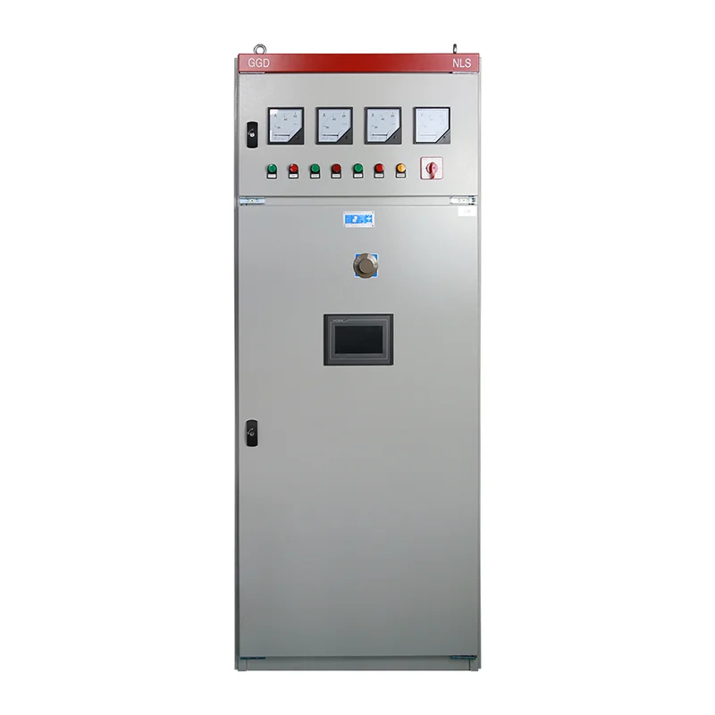
The PLC control cabinet for industrial automation is a real LINECOME product context for defining these requirements. Its exterior photograph does not establish which analog card is installed, its resolution, its diagnostic features or the scaling code delivered for a project. Those details belong in the approved bill of materials and software specification.
Provide the instrument list, ranges, wiring conventions and required reactions to invalid data with the inquiry. Ask for a channel-by-channel factory test record and a saved configuration baseline. Include how revisions will be reflected in drawings, program backups and the HMI so a successful initial test remains reproducible after maintenance.
For broader cabinet context, see what a PLC cabinet contains. Scaling acceptance is one part of that complete control system; it should produce evidence that can be traced from the transmitter requirement to the displayed and controlled quantity.
Learn the transmitter boundary
The RealPars video below distinguishes sensors, transducers and transmitters. It helps explain why the PLC receives a standardized electrical representation rather than the process quantity itself. Use it as background for reading the instrument schedule, while retaining the explicit equation and test record for actual scaling acceptance.
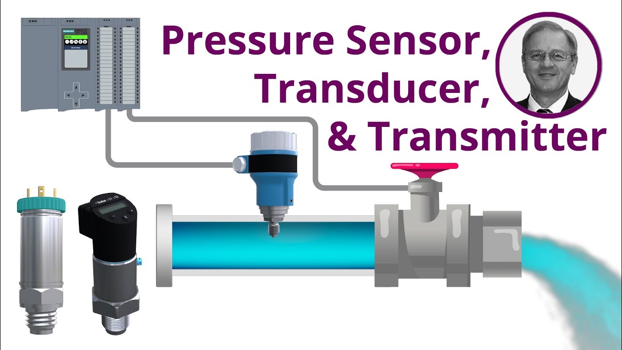
Video by RealPars. Watch Pressure Sensor vs Transducer vs Transmitter on YouTube.
Frequently asked questions
Does 4 mA always mean zero engineering units?
No. It means the configured lower endpoint of a linear 4–20 mA range. That endpoint might be zero, a negative temperature or another specified value. Read the transmitter configuration and use the matching engineering limit.
Can I reuse raw-count limits from another PLC?
Only after confirming that the actual module, configured range and data representation match. Different modules and settings can produce different values at the same current, so familiar constants are not sufficient evidence.
Should a failed signal display the minimum value?
Do not hide failure by replacing it with a normal minimum reading. Handle channel quality and data age separately, then apply the approved display and control behavior. The correct response depends on the process and its risk assessment.


