




A soft starter can reduce some pump shutdown pressure disturbances by controlling motor torque during a commanded stop, but a soft starter water hammer solution must be verified on the hydraulic system. A longer voltage ramp does not automatically produce a smooth flow reduction, and a normal soft stop cannot be assumed to work after the power supply disappears. First identify when the pressure event occurs, confirm the available stopping function, and coordinate the pump, check valve and pipeline response. Then accept the result using pressure and operating records, not just a quieter sound or a completed stop timer.
Identify which event actually causes the hammer
Start with the operating sequence. Does the disturbance happen when a stop command is issued, when a check valve closes, when another pump starts, when a control valve moves or when the station loses power? These events may sound similar but do not have the same available remedies. Save the time of the event, which pumps were operating and the valve and reservoir conditions.
Water hammer is a hydraulic transient associated with changes in liquid velocity. The pressure response depends on the pipeline and its boundaries, not just the electrical starter. The Ohio Water Environment Association presentation on pumping hydraulics identifies pump events, valve operation and other causes of transients, and discusses system-level control measures. Its examples are educational guidance rather than universal design limits for another installation.
Do not use noise alone to diagnose the problem. A check-valve impact, cavitation and mechanical vibration can require different investigations. Ask the pump and hydraulic engineers to distinguish the event using the operating state and suitable measurements before committing to a starter replacement.
Establish what the supplied starter can actually control
A conventional soft starter changes applied motor voltage during starting and, if equipped for it, stopping. It does not provide the same frequency-based speed command as a variable-frequency drive. The effect of reduced voltage on motor torque and the driven pump must be considered together. A stop-time setting describes a control action, not a guaranteed linear flow ramp.
Ask whether the offered unit has a basic voltage-ramp soft stop, a specific pump-control algorithm or another documented stopping mode. Obtain the manual for the exact model and firmware. Do not import parameter names or settings from another supplier’s guide, and do not assume that every product described as a soft starter offers the same pump functions.
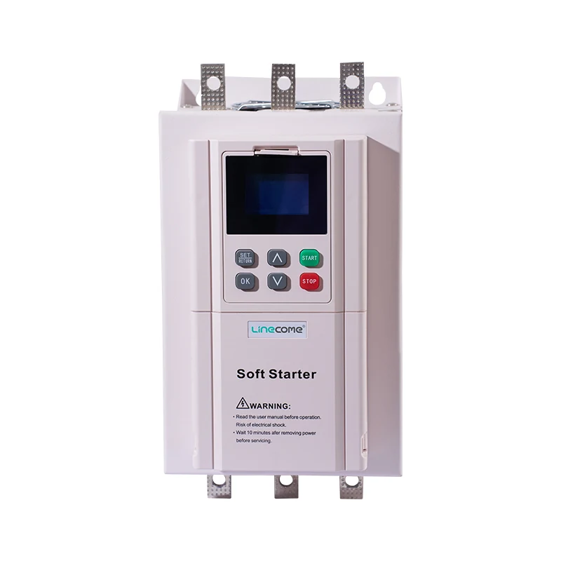
The LINECOME ZR900 online soft starter catalogue describes a soft-stop function and water-treatment applications. Confirm the delivered model, permitted motor duty and available stopping settings during the enquiry. The catalogue description is a reason to investigate the product’s suitability; it is not proof that the unit will eliminate surge on a particular pipeline.
Separate normal soft stop from emergency and power-loss behaviour
For a normal controlled stop, the required power and control sequence must remain available long enough for the intended action. If an upstream contactor opens immediately, a programmed ramp may not be executed as intended. Have the cabinet supplier document how the stop command, power devices and starter status signals interact. Verify the actual sequence rather than assuming that the PLC program and power circuit implement the same stop.
An emergency action may need a different response because personnel and machinery safety take priority over a preferred hydraulic ramp. Likewise, a utility outage can remove the energy needed for an ordinary soft-stop function. Specify these as separate operating cases. Do not delay a required protective action merely to preserve a normal shutdown sequence.
Review pressure retention, valve behaviour and surge protection for the unpowered condition with the hydraulic designer. A station that passes normal stopping tests can still have an unacceptable outage transient. This distinction should appear in the quotation and acceptance plan so responsibility for the missing operating case does not emerge only after installation.
Create a baseline before changing the ramp
Document the current system: pump model and curve, motor data, pipeline length and profile, operating flow range, static levels, check-valve type and any existing surge equipment. Include the combinations of pumps that can run together. The same pump can stop differently when another unit remains in operation or when the receiving level changes.
Establish a recording plan with the hydraulic engineer. Select pressure instruments and sampling suited to the expected transient, and identify measurement locations that can reveal the relevant positive and negative pressure behaviour. A slow control-system trend can miss a fast event. Ensure instrumentation and fittings are suitable for the service and pressure range.
Capture the stop command, starter state, valve events and pressure on a common timeline where practical. Record flow or speed when suitable instruments are available. A useful baseline states what happened before, during and after the stop, rather than presenting one peak number without its operating condition.
| Operating case | Information to retain | Acceptance question |
|---|---|---|
| Normal stop with one pump operating | Pressure trace, stop sequence and valve behaviour | Does the controlled stop meet agreed hydraulic limits? |
| One pump stops while another runs | Pump combination, remaining flow and pressures | Does interaction create a separate disturbance? |
| Check-valve closure event | Closure timing and pressure response | Is valve behaviour compatible with the deceleration? |
| Loss of utility supply | Approved outage assessment and available protection | What protects the line when normal soft stop is unavailable? |
| Restart after a stop | System state, permissives and pressure response | Can the next start occur without an unsafe condition? |
The table defines evidence to collect, not numerical pressure limits. Set allowable pressures, vacuum conditions and test boundaries from the pipeline design, component ratings and project requirements.
Commission soft stop as a controlled hydraulic experiment
Begin with the supplier’s approved settings and test procedure. Confirm that the pump has the required water supply, valves are in their permitted positions and the station can be operated safely. Agree who can stop the test and which observations require immediate suspension. Do not intentionally provoke a damaging pressure event to demonstrate that protection is needed.
Change one relevant setting at a time and retain the previous configuration. Compare pressure traces under comparable initial conditions. Watch for the point where useful pumping decreases and the check valve closes; that behaviour may not track the displayed ramp time. Increasing duration can add motor and starter heating without delivering the desired flow response.
Review the result with both the electrical and hydraulic parties. If the pressure event remains, reconsider the event’s mechanism, valve behaviour and the available control function rather than continuing to extend the same timer. Record unsuccessful tests as evidence. A good commissioning log explains why a setting was retained or rejected and prevents a later shift from repeating an unhelpful adjustment.
Check motor and starter duty as well as pressure
A smooth-looking stop is not acceptable if it exceeds the permitted motor or starter duty. Include starting and stopping frequency, actual current and the surrounding cooling conditions in the review. The thermal effect of a stopping function depends on the equipment and operating cycle. Ask the supplier to assess the full duty profile instead of selecting solely by motor power.
The related soft starter starts-per-hour guide explains why repeated and clustered operations need a duty assessment. Use it alongside the pump test record. Do not transfer a catalogue starts-per-hour figure to a different current, acceleration, soft-stop or ambient condition without confirmation.
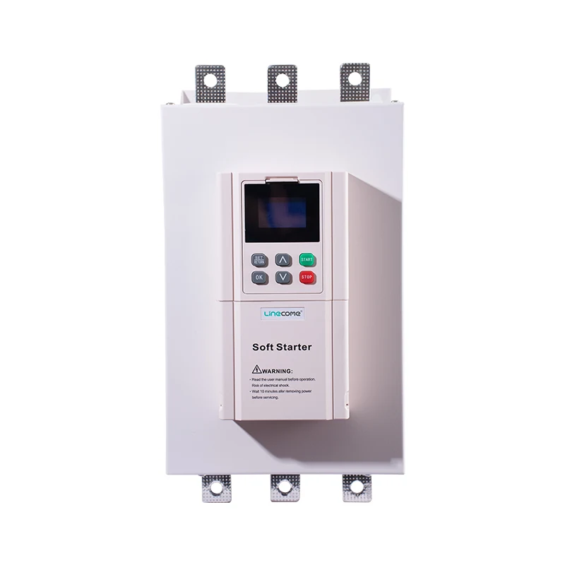
The photographs illustrate different ZR900 catalogue sizes. They support discussion of model selection and control interfaces; they are not photographs of a tested pump station and do not establish hydraulic performance. Match the actual supply, motor current, enclosure and operating sequence to the supplier’s confirmed offer.
Decide whether the remedy belongs in the pipeline
Some systems need measures beyond starter settings. Depending on the assessed transient, the hydraulic design may involve valve selection, surge equipment, air management, control sequencing or another change. Selection and sizing belong to the relevant specialist and must consider both normal and abnormal conditions. Adding a device because it worked on a different station is not a design calculation.
A VFD may be appropriate when controlled operating speed or process regulation is required, but it also needs hydraulic validation. It does not automatically solve every power-loss event. The separate VFD PID control guide for constant-pressure pumps addresses continuous pressure regulation, which is a different requirement from accepting a fixed-speed pump’s stopping transient.
For the soft starter’s electrical operating sequence, see how a soft starter works. Keep that principle separate from claims about a completed hydraulic design. A starter function and a verified system outcome are different pieces of the procurement evidence.
Learn the principle without treating a demonstration as design proof
Practical Engineering’s video below demonstrates hydraulic transients and why changes in flow matter. The Walkerton Clean Water Centre’s educational video directory includes this material among learning resources. Use the demonstration to understand the phenomenon; use project-specific measurements and analysis to decide how to protect an industrial pipeline.
Video by Practical Engineering. Watch What is Water Hammer? on YouTube.
Specify a handover that covers the entire stop sequence
The enquiry should identify the pump and motor, duty range, pipeline profile, operating levels, valve arrangement, existing surge equipment and the event requiring improvement. Ask the starter supplier to state the stopping function, required power sequence, supported signals and limitations. Ask the hydraulic designer to define acceptance limits and the normal, outage and multi-pump cases that must be assessed.
For maintenance or inspection, follow the site’s isolation procedure and control electrical, hydraulic and mechanical energy. The CCOHS hazardous-energy guidance explains that hazardous energy extends beyond the electrical supply. A stopped motor does not mean the pipeline is depressurized or safe to open.
At handover, retain final settings, synchronized test records, the verified operating envelope and the approved response to faults and power loss. List any unavailable test conditions and the party responsible for completing them. Give operators a clear method for recording recurrence, including pump combination and valve state, so future diagnosis begins with facts rather than another arbitrary ramp adjustment.
Frequently asked questions
Will increasing the soft-stop time always reduce water hammer?
No. A voltage ramp does not guarantee a matching flow ramp. Compare measured pressure and valve behaviour, verify the supplied stopping function and check thermal duty before accepting a longer setting.
Can a normal soft stop protect the pipeline during a power failure?
Do not assume that it can. Loss of supply is a separate design case because the normal stopping function may no longer have the required energy available. Assess the pipeline’s outage response and surge protection independently.
What should prove that the adjustment worked?
Use agreed hydraulic limits and recorded tests under the relevant operating conditions. Retain pressure traces, pump and valve states, stop settings and thermal-duty checks. Reduced noise alone is insufficient acceptance evidence.


