




VFD PID control for a constant-pressure pump uses pressure feedback to adjust motor speed as water demand changes. The controller compares a pressure setpoint with the measured pressure and changes the speed command to reduce the difference. Reliable operation requires correct transmitter scaling, the right control direction, sensible speed limits and independent protection against conditions such as dry running or excessive pressure. Tuning the controller is only one part of commissioning; the pump curve, piping system and sensor location must also support the intended operating range.
This guide addresses ordinary industrial and building-water centrifugal-pump applications. It is not a fire-pump control design or a substitute for a regulated safety system. For the wider application context, see our HVAC fan and pump drive guide. For projected electricity savings, use the separate VFD energy savings calculation rather than treating a stable pressure trace as proof of savings.
Define what pressure the system actually needs to hold
Constant discharge pressure, constant differential pressure and pressure at a remote point are different objectives. A transmitter near the pump may show stable discharge pressure while users at the far end of a long line experience a pressure drop. A closed hydronic loop may need differential pressure across a selected part of the network rather than pressure relative to atmosphere.
Agree the measurement location, pressure type, required range and operating limits before selecting the controller. Record the minimum useful pressure as well as the maximum permitted pressure. If the most demanding branch changes during operation, a fixed local setpoint may require a different control strategy. Avoid compensating for poor sensor placement simply by increasing the target pressure everywhere.
The Hydraulic Institute’s pump application FAQs describe why pump operating conditions and system requirements matter. The controller cannot make an unsuitable pump operate acceptably at every combination of flow and pressure. The selected operating region must remain within the equipment’s documented limits.
Understand the feedback loop before adjusting gains
The setpoint is the desired pressure. The process variable is the measured pressure. The controller output becomes a speed or frequency command, subject to the drive’s limits and operating mode. If demand increases and pressure falls, a typical booster system needs more speed. If demand decreases and pressure rises, it usually needs less speed. Confirm that expected physical response for the actual system.
Proportional action changes output in response to present error. Integral action accumulates error over time and helps remove sustained offset. Derivative action responds to the rate of change and may amplify measurement noise if applied without suitable treatment. Many pumping loops use proportional and integral action without derivative, but the correct choice depends on the process and controller implementation.
Parameter names can be misleading across controllers. “Integral time” and “integral gain” can have opposite numerical effects: a shorter integral time commonly means stronger integral action, while a larger integral gain commonly means stronger action. Read the exact equation or manual description. A value copied from another drive family can be inappropriate even when both displays use the label PID.
Scale the pressure transmitter in engineering units
Confirm the transmitter output type, measuring range, power requirements and drive input configuration. A current input, voltage input and a digitally received pressure value require different setup. Use the correct documentation for the exact input terminals and signal common. This article does not provide a universal wiring diagram because terminal assignments and allowable connections vary.
For an illustrative 4–20 mA transmitter covering 0–10 bar, pressure is p = (I − 4)/16 × 10, with I in mA and p in bar. Therefore 4 mA corresponds to 0 bar, 12 mA to 5 bar and 20 mA to 10 bar. These are arithmetic examples, not product specifications. A transmitter with an offset or different range needs a different equation.
| Illustrative signal | Scaled pressure | Commissioning check |
|---|---|---|
| 4 mA | 0 bar | Confirm the configured low endpoint |
| 8 mA | 2.5 bar | Verify a point between the endpoints |
| 12 mA | 5 bar | Compare with a suitable reference measurement |
| 20 mA | 10 bar | Confirm the high endpoint without exceeding process limits |
The table assumes a linear 0–10 bar transmitter with a 4–20 mA output. Verify scaling through an approved instrument test method; do not create an unsafe process pressure just to test the upper endpoint. Also check how the controller displays units and handles readings outside the expected range.
Verify control direction with a controlled test
A reversed control direction can turn negative feedback into positive feedback. Pressure rises, the controller increases speed, and pressure rises further. Controller terms such as direct or reverse action are not consistent enough to justify guessing. Check the manual, then verify the actual response with a small permitted change and the process under supervision.
Begin with output constrained to an approved range. Confirm the relationship between speed and measured pressure before enabling automatic control. If the feedback falls while real pressure rises, investigate sensor polarity, scaling or measurement placement. Do not tune around a fundamentally incorrect measurement. A stable-looking value on the display is not enough if it represents the wrong pressure variable.
Set the operating envelope before tuning
Minimum speed must account for the pump, motor, cooling, flow and system requirements. Maximum speed must respect the pump and motor ratings and the mechanical installation. Static head can prevent useful delivery below a certain speed, while low flow may cause unacceptable operation even when the motor remains electrically comfortable. Obtain the relevant pump limits from the manufacturer.
The DOE’s variable-speed pumping application guide explains why speed control must be evaluated against system characteristics. The controller’s output range should reflect the validated operating envelope. A lower frequency limit chosen only to make the loop appear quieter can conceal an unsuitable operating point.
Acceleration and deceleration limits also affect the loop. If the pressure controller asks for a speed change faster than the drive can execute, the actual response lags the control output. Tuning should account for that delay. Excessively restrictive ramps can produce slow recovery; excessively aggressive ramps may cause hydraulic disturbances. Validate the complete response rather than optimizing each parameter independently.
Tune gradually under representative demand
First confirm scaling, control direction and safe manual operation. Record the starting settings and the test condition. Use a modest permitted setpoint or demand change and observe pressure, controller output and actual frequency together. Keep a record of overshoot, settling behavior, sustained oscillation and whether the output reaches a limit.
Adjust one tuning factor at a time. Too much proportional action may make the output react sharply to small errors or noisy feedback. Integral action that is too aggressive may cause overshoot and repeated corrections, especially with delay or saturation. Integral action that is too weak may leave the pressure offset for too long. The right settings depend on process volume, sensor dynamics, pump characteristics and the controller’s own implementation.
When output is constrained at a minimum or maximum, integral accumulation can cause slow recovery after demand changes. Check whether the controller provides anti-windup behavior and how it works. Do not assume that every drive offers the same feature. If a PLC and drive both provide pressure control, identify which device owns the loop; two active controllers correcting the same pressure can interfere with each other.
Plan for low demand, sleep and restart
At very low demand, a controller may hold the pump at minimum speed even though no useful flow is required. A suitable sleep function can stop the pump under defined conditions and restart it when pressure falls or demand returns. The design must account for storage volume, leakage, pressure decay, minimum run time and acceptable cycling frequency.
Sleep should not be enabled merely because the drive menu includes the option. A leaking nonreturn valve or a very small pressure vessel can produce repeated starts. Test low-demand periods and record both pressure and starts per hour. Use the equipment supplier’s limits for restart frequency and minimum flow; this guide does not prescribe universal timing or pressure thresholds.
Keep protective functions independent of ordinary pressure regulation
Pressure regulation cannot by itself prove that the pump has water available. A sensor fault can produce a plausible-looking signal. A blocked discharge, dry suction, failed transmitter or control communication loss may require a dedicated detection and shutdown response. Define the required behavior for each condition as part of the system design.
For example, loss of pressure feedback should not automatically command maximum speed unless the system has been specifically designed and assessed for that response. Confirm transmitter-fault detection, alarm handling, permitted restart and any manual-reset requirement. Mechanical pressure protection and other safeguards remain separate from an ordinary PID setpoint. The proper arrangement depends on the process and applicable requirements.
Acceptance tests and records for handover
Test representative high, medium and low demand, including start, normal stop, sleep and restart where used. Confirm pressure at the point that actually matters to users. Verify that the pump remains within its acceptable operating region and that changing demand does not create unacceptable pressure excursions. Record the test duration and operating conditions so the results can be interpreted later.
The DOE’s pumping system sourcebook supports evaluating the complete installation. Maintain a handover record containing the sensor range, scaling, setpoint, output limits, active ramps, tuning values, alarm responses and backup configuration. Energy monitoring belongs in a separate comparison of equal useful service, not a claim based only on lower speed.
Prepare a complete LINECOME application enquiry
Send the motor nameplate, supply details, pump curve, system head information, pressure measurement location, transmitter data, demand range and the required fault behavior. Ask which device will run the control loop and which functions are available in the exact quoted drive. Confirm the signal interface and software requirements before ordering.
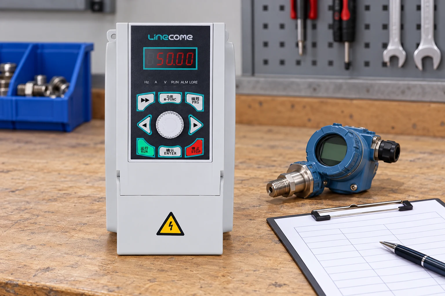
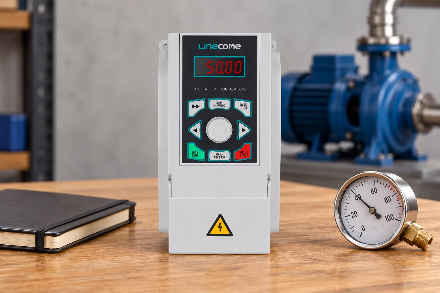
Use the LINECOME LNC820 range as a starting point for a model discussion and the product hub to compare other families. Before field work, review our installation and commissioning checklist. The illustrations show the existing product’s appearance in conceptual scenes; they do not demonstrate a wired or approved pump installation.
Further learning
The Engineering Mindset’s independent VFD explanation introduces the electrical stages that make speed adjustment possible. Use it as background; pressure-loop commissioning still requires the actual drive manual, pump data and site measurements.
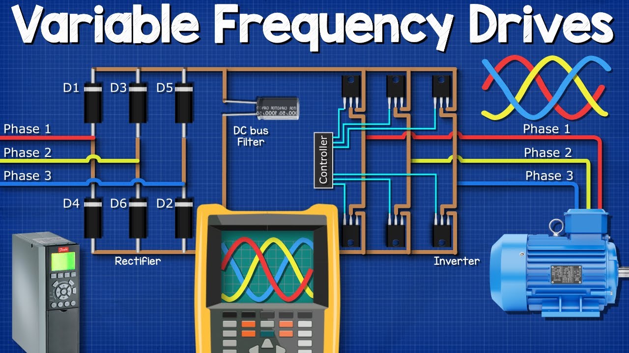
Watch the VFD explanation on YouTube.
Frequently asked questions
Does constant pressure mean constant flow?
No. Flow normally changes with demand while the controller attempts to maintain the selected pressure variable.
Can I copy PID settings from another pump?
Not reliably. Pump, piping, sensor and controller differences can change the response. Begin with equipment guidance and validate the actual system.
Should a pressure controller always use derivative action?
No. Many pumping loops use proportional and integral action. Derivative needs a specific justification and suitable handling of measurement noise.
Does PID control protect against dry running?
Not by itself. Dry-run detection and its response need an appropriate, separately defined protective arrangement.


