




Soft starter current measurement is meaningful only when the meter and the starter display describe the same conductor, operating stage and current quantity. Before changing a current limit or overload setting, verify the sensing arrangement, current-transformer scaling, instrument suitability and bypass path. A disagreement during acceleration does not by itself prove that either device is faulty. This guide sets out a commissioning record for ordinary industrial motor circuits; it does not authorize live work or replace the exact equipment instructions.
Define the reading you need before connecting an instrument
Write the question first. Are you checking the motor’s running load, the highest current during acceleration, the starter’s current-limit response, or the value transmitted to the control system? Those are different measurements. A handheld display observed at an arbitrary moment cannot establish all four. Specify whether the reported value is one phase, an average of phases, a peak capture or an RMS quantity over a defined interval.
Record the start command, acceleration period, full-speed transition and bypass indication against the measurement timeline. A current trace with these events identified is more useful than a photograph showing a single ampere value. Keep the process condition alongside it: an unloaded motor and a pump delivering against its normal system pressure do not represent the same test. The companion explanation of soft-starter operation covers the sequence; here the concern is whether the measurement follows that sequence correctly.
Establish a safe and repeatable test arrangement
Measurements inside energized motor equipment require competent personnel, appropriate instruments and a planned method. Follow the site’s isolation procedures for installing or changing test connections. The HSE guidance on electrical equipment explains the importance of competent work and suitable precautions. Do not improvise exposed connections to obtain a more convenient display.
For conventional current-output current transformers, never disconnect the secondary while primary current is flowing. Dangerous secondary voltages can result. The Michigan State University current-transformer technical note discusses CT operation and this safety issue. Identification matters: a current-output CT, a voltage-output transducer and a Rogowski system require different interfaces. A device that fits around a cable is not automatically compatible with a starter input.
Prepare a test sheet before the motor starts. Include the circuit reference, instrument identity, current range, calibration status, measurement location and person responsible for stopping the test. Agree the conditions that end the test, such as unexpected mechanical behavior or a protection operation. A repeatable method reduces the temptation to restart a hot motor simply because one reading was missed.
Trace the actual current path through acceleration and bypass
Use the approved power drawing to identify which conductors pass through which sensors. Mark the starter power section, external bypass branch, motor branch and any independent overload sensing. Follow the drawing through each operating stage. A sensor in a semiconductor-only branch may not observe the same current after an external bypass contactor closes. The exact arrangement determines whether the starter continues to measure motor current.
Do not infer sensor coverage from the front-panel current display remaining visible. It might show a retained value, a calculated quantity or a live measurement through a different path. Confirm the manufacturer’s description and compare the configured monitoring behavior with the as-built wiring. For bypass design details, use the project’s accepted circuit rather than adding a CT because another cabinet used one.
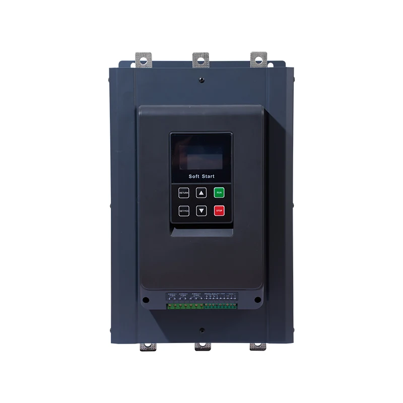
A related PR800 external-bypass soft starter provides a product reference for discussing this architecture. Its product photograph does not identify the complete project current path or establish an external CT requirement. Request the wiring diagram and sensing description for the selected rating before specifying accessories.
Check scaling without confusing the motor setting and CT ratio
The motor rated-current setting, a CT primary rating, a CT secondary rating and a PLC analog scaling range are separate data items. Copy each from the appropriate nameplate or approved configuration record. A replacement sensor can have the same physical dimensions and a different output. Preserve the units as well as the numbers; a current signal and a voltage signal are not interchangeable.
For a conventional ratio illustration, suppose a CT is marked 200/5 A. Its nominal ratio is 40:1. Under the ideal ratio relationship, a 2 A secondary corresponds to 80 A primary: primary current equals secondary current multiplied by the ratio. This arithmetic is an educational example, not a recommended CT size or a field test instruction. Actual accuracy depends on the sensor specification, burden and operating conditions. Do not apply this relationship to a device with an integrated voltage output or to a different sensing technology.
Now follow the value to the operator screen. If the starter sends a current value through an analog output or network register, check the output range, data representation, engineering units and PLC scaling separately. A correct local display with an incorrect control-room display usually warrants a signal-chain review before the power circuit is altered. Record the expected value at each interface so that a later service engineer can repeat the comparison.
Select an instrument for the waveform and the test question
During soft starting, the controlled voltage and resulting current are not necessarily sinusoidal. A meter intended only for sinusoidal waveforms can therefore give a misleading comparison. Check the instrument manufacturer’s statement on waveform capability, crest factor, bandwidth, range and capture interval. A true-RMS label is useful information, but it does not establish suitability for every start transient or every current magnitude.
Equally, the starter’s displayed current may be filtered or averaged. Some manufacturers describe their displayed current as a phase average or define a particular measurement basis. Read that definition before comparing it with a single-phase external instrument. The starting-current measurement overview addresses supply-side observations; a commissioning comparison should explicitly identify whether both readings represent the motor branch or different points in the installation.
Compare steady running values first when the process allows it. Then capture the acceleration interval using an approved instrument and synchronized event markers. This separates a persistent scaling error from differences caused mainly by sampling and display update speed. Avoid treating the maximum value briefly seen by an operator as an independently verified peak measurement.
Use a disagreement table to choose the next check
The following table is a qualitative diagnostic plan based on tracing the current path and measurement chain. It contains no universal accuracy tolerance. Use the exact sensor and instrument specifications to set acceptance limits.
| Observed disagreement | Evidence to collect | Next check before changing settings |
|---|---|---|
| Constant proportional error at steady load | CT label, configured ratio, external instrument range | Verify ratio and engineering-unit scaling |
| Agreement before bypass, disagreement afterward | Bypass status and marked power drawing | Trace which sensor remains in the motor path |
| Only the acceleration maximum differs | Time-aligned traces and capture settings | Compare sampling interval and waveform capability |
| Local starter agrees, HMI disagrees | Local value, transmitted register or signal, HMI units | Check communication representation and PLC scaling |
| One phase differs consistently | Individual phase readings at the same load | Check sensor identification, wiring and real phase behavior |
| Readings vary between repeated starts | Load state, thermal condition and supply observations | Restore comparable conditions before drawing conclusions |
Do not use this table to dismiss an actual electrical fault. An abnormal phase reading can reflect a real circuit problem as well as a measurement issue. Stop when the approved operating limits or test conditions are exceeded. Preserve the raw readings rather than editing them into a smoother commissioning graph.
Separate measurement correction from protection decisions
A calibration adjustment should follow a documented manufacturer procedure and a trusted reference. It should not be a convenient way to make two displays agree. First establish which quantity each device measures, then identify whether the difference exceeds the stated tolerance under a valid comparison condition. Record any authorized correction, the previous value and the reason for the change.
An overload operation needs its own investigation. Changing the motor current setting to match a suspect meter can reduce protection effectiveness. Conversely, a low displayed value does not prove that the motor is lightly loaded if a CT or signal range is wrong. Use the separate soft-starter overload-trip checklist when protection has operated, preserving the trip information and thermal history.
Build the purchase and acceptance package
For a new cabinet, ask the supplier to identify the sensing method, current display definition, measurement coverage in bypass, approved external interfaces and any restrictions on replacement CTs. Include the motor nameplate, supply arrangement, starting duty and control-system reporting requirements. Ask for the exact manual revision and the approved circuit for the chosen rating; a general family brochure is insufficient for wiring acceptance.
The completed report should contain the untouched instrument export, a marked drawing, event timing, process condition and a comparison table with units. State which operating stages were tested and which remain open. If only steady running was checked, say so. Keep any unexplained disagreement as an unresolved item with an owner and a next test rather than signing off the whole measurement chain.
Further learning: the starting sequence
The educational video below explains the basic soft-start sequence. Use it to recognize the acceleration and running stages when preparing a measurement timeline; it does not define CT compatibility, accuracy or test limits for a particular product.
Video by RealPars. Watch What is a Soft Starter? (For Absolute Beginners) on YouTube.
Frequently asked questions
Why does the clamp meter disagree only during starting?
The devices may use different sampling intervals, waveform processing or current definitions. Verify the external instrument’s suitability and the starter’s display definition, then compare time-aligned readings under the same load before concluding that calibration is wrong.
Can I replace a current transformer with any unit having the same primary rating?
No. Secondary output, burden, accuracy, wiring and compatibility with the receiving device also matter. Use the approved sensor specification and replacement procedure. Conventional current-output CT secondaries must not be opened while primary current flows.
Should I increase the overload setting to match a higher meter reading?
No adjustment should follow from that disagreement alone. Establish the correct measurement basis, verify motor and protection configuration, and investigate the load and trip evidence. Change protection only under the approved equipment and motor-protection procedure.


