




PLC input debounce accepts a digital state only after it remains stable for a defined period. It can prevent a pushbutton or ordinary process contact from producing several events during one operation, but excessive filtering can hide legitimate pulses and delay a response. Choose the delay from measured chatter and the shortest valid event, then test the complete input-to-action path. There is no universal debounce time for every PLC, sensor or machine. Safety functions require their own approved design and validation.
Decide whether the problem is contact chatter or something else
Start with the physical event. A mechanical contact can open and close repeatedly as its surfaces settle. A sensor can also switch repeatedly because the target vibrates at its detection boundary. Electrical interference, an unstable supply or a loose connection can produce superficially similar symptoms. These causes call for different repairs even if a longer timer makes the screen look calmer.
The Arduino debounce example illustrates the basic problem of multiple transitions from one pushbutton operation. It is useful for understanding the principle, not for choosing an industrial PLC’s terminals, voltage levels or timing settings. The University of Nebraska laboratory exercise also treats bounce duration as something to investigate rather than assume.
Describe the observed failure precisely: two counts from one press, an intermittent permissive, a missed product or a repeated alarm. Record whether the input module indicator, the PLC variable and the HMI all show the same behavior. A slowly updated HMI can conceal short changes or display stale states, so screen observation alone is not enough to characterize a contact.
Confirm the electrical input before adding a timer
Use the approved drawing to identify the contact type, sensor supply, input common and receiving channel. Verify that the device output and module input are compatible. A timer cannot correct a wrong sinking/sourcing arrangement or an absent reference connection. The separate PLC input compatibility guide addresses that electrical boundary.
Check the supply under the conditions in which chatter occurs. Look for terminal damage, loose actuator mounting, poor cable routing and a sensor target near the edge of its operating range. Investigate recurring faults when motors or contactors operate. If the control supply is suspect, use the 24 V DC voltage-drop checks before deciding that the sensor needs a longer software delay.
Do not work on live terminals just to confirm a theory. Follow the site’s isolation and test procedures, and have competent personnel collect the required evidence with suitable instruments. Keep safety-related inputs outside this ordinary process-control exercise. Their permitted timing, fault response and architecture must come from the validated safety design.
Map every stage between the contact and the action
A digital input does not travel directly from the field contact to a program instruction. The path can include sensor response time, module filtering, input transfer, program-task execution, software qualification, output transfer and actuator response. The application may also use remote I/O or communication updates. Each stage can change when an event becomes visible.
The University of Lisbon PLC teaching material explains the relationship between input acquisition, program execution and output updates. Actual controllers can offer additional tasks and immediate or event-based functions. Identify the configured path for the channel rather than assuming the simplest cyclic model applies everywhere.
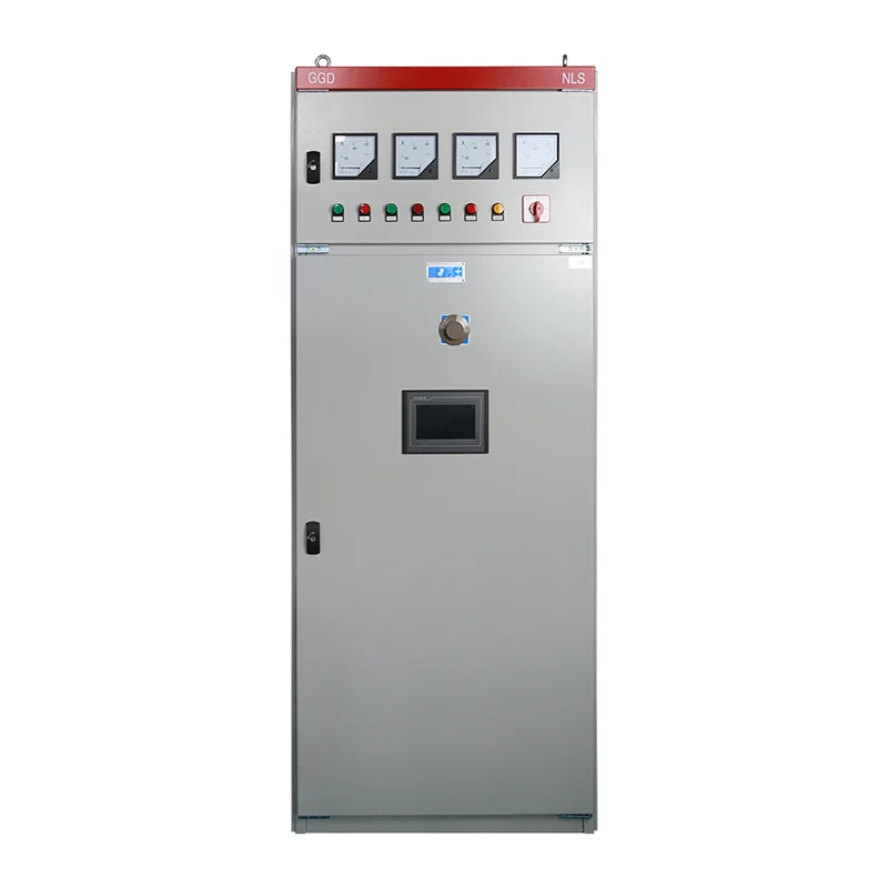
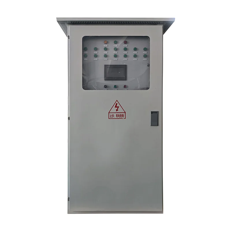
For an ordinary PLC control cabinet, request the controller model, input module reference, filter configuration and program version. A cabinet photograph demonstrates the product category, but it cannot prove that a specific input supports a particular filter range or high-speed counting function. Those details belong in the equipment schedule and configuration backup.
Give hardware filtering and software qualification separate jobs
An input module filter acts before the program sees the channel state. A software debounce acts on the value available to the executing task. This distinction matters because software cannot recover a pulse that the module filter has already rejected. It also cannot reliably characterize a transition that occurs entirely between ordinary input observations.
Use the module documentation to establish whether the filter applies to one channel or a group, whether rising and falling transitions have the same treatment, and whether high-speed functions use separate settings. Changing a grouped filter for a troublesome pushbutton can inadvertently alter a nearby pulse input. Record every affected channel before downloading a revised configuration.
A software qualification block can require a continuously true state before accepting ON and a continuously false state before accepting OFF. Reset the pending qualification when the raw input returns to the previously accepted state. This describes the intended behavior; the actual block must follow the controller’s timer semantics and task execution rules. Do not insert a blocking wait that delays the rest of the control program.
Keep raw and accepted values distinct and clearly named. Ordinary sequence logic should use the agreed qualified value consistently, while diagnostics may display both. Mixing raw and filtered states across different interlocks can create contradictory behavior during the qualification interval. Include that interval in the operator’s understanding of the signal rather than treating it as invisible.
Select timing from both unwanted and valid events
Measure the unwanted transitions and define the shortest event that must be accepted. The available margin between them determines whether simple time qualification is appropriate. If chatter lasts nearly as long as a legitimate event, there may be no suitable delay. Repair the mechanics, improve the sensing method or use an appropriate capture interface instead of forcing a timer to separate indistinguishable signals.
Consider a planning example with deliberately hypothetical values. A normal product signal remains high for at least 80 ms, while observed chatter ends within 8 ms. A candidate 15 ms ON qualification might appear reasonable, but it still requires checking the module filter, task timing and operating variation. The 15 ms value is not a recommendation for any product; it simply demonstrates why both the rejected disturbance and accepted event must be measured.
Response delay also creates positional error on moving equipment. For constant speed, distance equals speed multiplied by delay. At an illustrative speed of 0.5 m/s, an added 20 ms delay corresponds to 0.01 m, or 10 mm, of travel. This calculation assumes constant speed and isolates only that added delay. Real response includes the rest of the signal and actuator chain. Position-sensitive functions need an agreed total response budget.
Test the conditions that reveal hidden failures
A single deliberate button press is insufficient. Test slow operation, rapid repeated operation, a held contact, release, startup and transitions near the shortest accepted duration. Where the approved test setup permits, introduce brief disturbances shorter than the qualification interval and verify that they do not create accepted events. Record the injected signal and the observed accepted state.
| Test condition | Expected evidence | What a failure suggests |
|---|---|---|
| One complete ordinary button operation | One intended accepted event | Chatter or duplicate edge processing |
| Contact held continuously | Stable accepted state without repeated counts | Counting level instead of the required edge |
| Brief unwanted transition | Raw change with no accepted event | Inadequate filtering or inconsistent variable use |
| Shortest valid process pulse | Event accepted throughout specified operating range | Excessive delay or unsuitable input capture |
| Contact releases with chatter | Defined OFF behavior | Missing or unsuitable OFF qualification |
| Controller restarts with contact already active | Documented initial state and restart behavior | Unspecified initialization or false edge generation |
| Other channels operate simultaneously | Their valid events remain visible | Unintended grouped filter changes |
This is a functional test plan, not a certification method. Set exact durations and pass limits from the approved process requirements and module instructions. Keep test conditions repeatable and distinguish injected simulation from tests performed with the actual field device.
Treat counters and safety signals as separate design questions
A fast pulse source needs an input and capture method suited to its frequency, minimum high time and minimum low time. A software edge detector on an ordinary cyclic input is not automatically equivalent to a high-speed counter. Check the complete module specification and expected pulse shape before accepting a counting solution.
Safety inputs require a validated response time and fault behavior. Do not apply the ordinary debounce example to an emergency stop, guard or protective device merely because its contact chatters. Investigate the fault and use the permitted safety-controller configuration and validation procedure. A quiet indication is not evidence that the protective function remains correct.
Startup also deserves a written rule. If a pushbutton is held during power restoration, should the application accept its level, require release before another command, or report a fault? The answer depends on the machine design. Test the agreed behavior without allowing an unintended restart, and preserve it when a debounce block is revised.
Hand over a signal record that maintenance can use
For each qualified input, record the terminal, field device, module channel, hardware filter, software ON and OFF conditions, shortest valid event and program version. Attach representative timing evidence and the acceptance results. Make the difference between observed behavior and specified limits visible in the record.
Keep the raw signal available for diagnosis without letting it bypass the intended control logic. If chatter worsens over time, maintenance should be able to detect that deterioration rather than continually increasing the delay. The wider PLC cabinet component guide explains the hardware context; this signal-level record connects that equipment to the actual process behavior.
Further learning: the PLC and its inputs
The educational video below introduces the PLC, its inputs and the program that connects field signals to control actions. Use it as background for the signal path discussed above. The module manual and the measured application timing remain the basis for choosing an actual filter.
Video by RealPars. Watch PLC Basics | Programmable Logic Controller on YouTube.
Frequently asked questions
Is there a standard PLC input debounce time?
No single delay suits every contact and process. Measure the unwanted transitions, establish the shortest valid signal and total permitted response time, then test the candidate settings with the actual input module and program execution path.
Can software recover a pulse rejected by the input filter?
No. Once the input module has removed a transition before transferring its state, ordinary software has no event to recover. Choose appropriate module settings or a suitable capture function when short pulses must be retained.
Should both ON and OFF transitions be filtered?
That depends on the required behavior. Some ordinary contacts need qualification in both directions, while other signals require prompt release. Specify each transition separately, test initialization and avoid applying ordinary process filtering to safety functions.


