




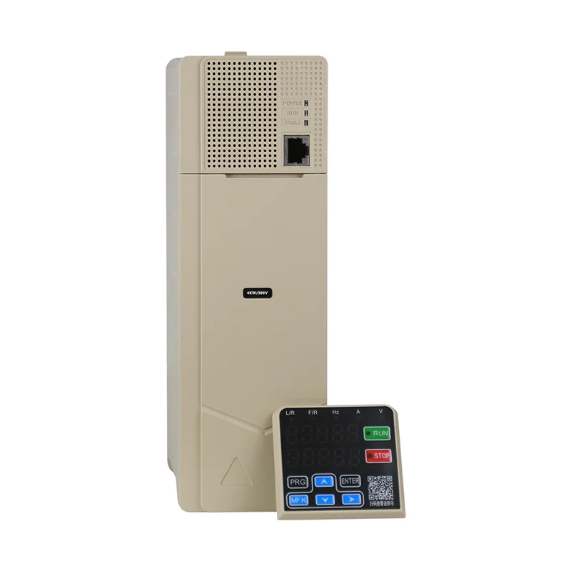
3 phase motor amp after vfd questions almost always mean three different amp readings got mixed together: motor full-load amps on the nameplate, the drive’s rated output current to the motor, and the higher line-side input current the VFD draws while it runs or accelerates the load.
After you install a variable frequency drive, the motor still has a nameplate FLA, but the amps you measure at the motor terminals and at the drive input follow the drive’s output frequency, load torque, and efficiency—not a single “after VFD” number copied from search snippets.
Use the Variable Frequency Drive hub to compare drive families once you know which amp column governs your decision.
For branch breaker and feeder handle sizing on small 230 V feeds, read the dedicated 6 amp 230 V VFD breaker size guide—this page stays on motor versus drive current after the VFD is in circuit, not upstream protection tables.
 .
Why “motor amps after VFD” searches mix three different amp numbers
Buyers paste one amp value from a nameplate and assume it still describes every meter reading once a drive sits between the utility and the motor.
Maintenance logs often show motor FLA, drive output current, and line input current on the same work order even though each answers a different question. Procurement may inherit a “six amp motor” note from a conveyor spec while the integrator sizes from the drive manual’s input column. Confusing those fields is how projects end up with the right motor but the wrong drive row or the wrong discussion about upstream protection.
Motor full-load amps (FLA) vs VFD output current during run
Motor FLA describes the load at rated speed and torque on the nameplate conditions; drive output current is what the inverter actually delivers at the operating point you commanded. Motor fla vfd worksheets should list both numbers side by side before you pick a catalog row.
On a fixed-speed installation, FLA and line current to the motor are closely related at steady state. With a VFD, output current can be lower than nameplate FLA when the machine runs below base speed on a variable-torque fan or pump, and it can approach or exceed FLA during heavy acceleration or constant-torque overload intervals. That is normal drive behavior—it does not mean the nameplate “became wrong after the VFD.”
| Reading | What it describes | Typical buyer mistake |
|---|---|---|
| Motor FLA | Thermal design point at rated duty on nameplate | Treating FLA as the only drive output limit |
| Drive output current (display or meter) | Real-time inverter current to the motor | Expecting it to equal FLA at every speed |
| Measured motor line current | What the windings see at the terminals | Comparing to branch breaker sizing without context |
Encyclopedic summaries of variable frequency drives note that the drive adjusts voltage and frequency together so torque can be controlled across a speed range. That control is why output current tracks operating point, not a fixed nameplate snapshot.
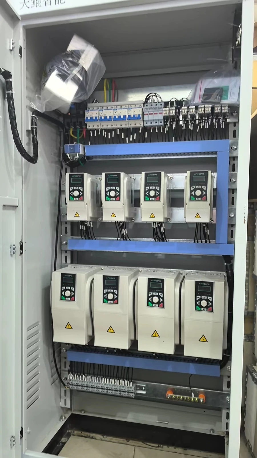 .
VFD input current on the line side after you install the drive
Line-side input current is what matters for feeder capacity and upstream device coordination; it is not interchangeable with motor FLA or with the current shown on the motor side of the drive.
The rectifier and DC link draw current from the supply with a different waveform and power factor than a direct-on-line motor. During acceleration or heavy torque, input current can rise even when the motor is still below nameplate speed. Integrators therefore quote drive rated input current from the manual when they discuss supply conductors—not the six-amp motor FLA alone.
Department of Energy material on adjustable-speed drives emphasizes matching motor speed to load requirements; the same planning mindset applies to reading input versus output columns on drive rating tables rather than assuming one amp number flows unchanged through the cabinet.
| Document column | Use in planning | Do not use it for |
|---|---|---|
| Motor FLA | Motor thermal verification, baseline load story | Line-side breaker sizing by itself |
| Drive rated output current | Picking a drive row for the motor | Utility service upgrade decisions alone |
| Drive rated input current | Feeder and upstream device discussions | Declaring motor shaft torque |
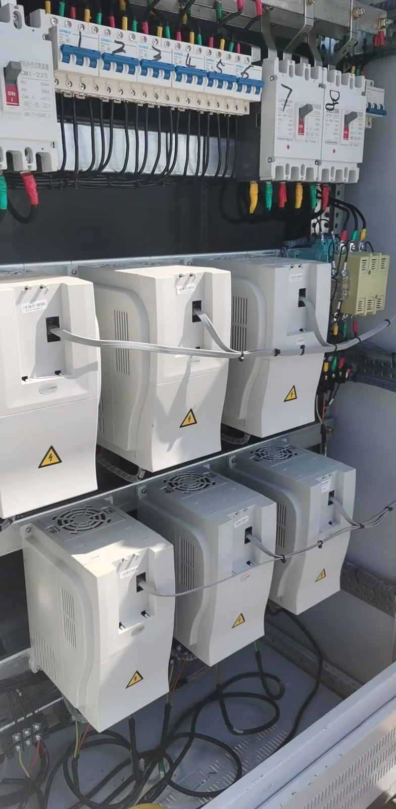
Acceleration, overload, and short-duty peaks buyers confuse with FLA
Short overload bands and ramp profiles can push displayed amps above steady FLA without meaning the motor is “over nameplate forever.”
Public LNC610 specifications document overload capacity for G-type machines in the product table—buyers should read that row as a time-limited drive capability, not as permission to ignore motor thermal limits or nameplate duty. Acceleration times you program also change how long current stays elevated during starts.
Community threads on VFD sizing repeatedly separate steady-run current from start and overload peaks. Treat peak readings as events to compare against drive overload curves and motor data, not as a replacement for FLA on the nameplate.
Important: A momentary amp reading on the drive display after startup is not, by itself, proof that the motor or drive is mis-sized—compare duration, duty class, and the manual’s overload wording before you change equipment.
 .
How to read nameplate, drive manual, and motor data side by side
A three-column worksheet prevents “motor amp after VFD” RFQs from shipping with only one number circled.
Start with motor nameplate: voltage, frequency, FLA, service factor, and duty if listed. Open the drive manual for the same motor voltage class and copy rated output current and rated input current for the frame you are considering. Add operating context: base speed, minimum speed on variable-torque loads, and whether the process needs heavy starts or frequent reversals.
| Worksheet row | Source document | Question it answers |
|---|---|---|
| Motor FLA | Motor nameplate | What is the rated load current at nameplate speed? |
| Drive output rating | Drive manual / catalog table | Does this frame cover the motor at expected duty? |
| Drive input rating | Drive manual / catalog table | What does the line side need during run and start? |
| Observed run current | Drive display or clamp meter | What is the machine doing at this speed and torque? |
Electrical Engineering Stack Exchange threads tagged for VFDs often remind readers that input current, output current, and motor FLA appear on different pages of the documentation set—this worksheet keeps them aligned for procurement packets.
Common sizing mistakes when someone only knows a low motor amp number
A single low amp number on the motor sticker is a starting clue, not a complete drive or feeder specification after a VFD is added.
Teams sometimes pick a drive by matching six amps on the nameplate to the smallest catalog row, then discover input current or overload requirements need the next frame up. Others copy motor FLA into breaker discussions even though branch protection for the VFD feed belongs to a separate checklist—as covered in the site’s breaker sizing article for small 230 V drives.
Another frequent error is ignoring minimum speed and cooling on fan and pump loads: output current may look modest while airflow or flow is insufficient. Variable-torque savings stories from authority sources still require engineering review on constant-torque or low-speed duty.
For inverter internals and PWM behavior that explain why current differs from line to drive to motor, link out to how a VFD works rather than duplicating mechanism prose here.
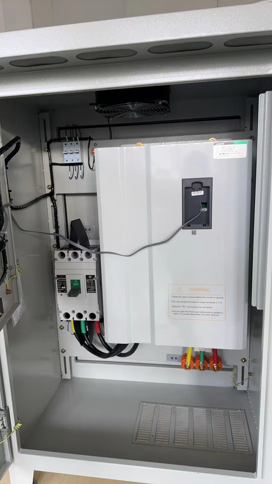
Matching LNC610 and LNC820 drives — product fit by motor amp band
Published catalog tables give rated input and output amp columns; your job is to map motor FLA and duty into the correct row—not to assume one nameplate amp selects everything.
When you need site-backed examples, the LNC610 general-purpose VFD series page lists rated output and input currents per kW row on the public table, along with V/F and open-loop vector modes and built-in PID on series marketing. Compare motor FLA and expected overload behavior to those columns, then confirm acceleration, braking, and fieldbus needs.
The LNC820 general-purpose VFD series page publishes similar rated current columns on native single-phase and three-phase input models in the 0.75–2.2 kW band—useful when line-side input current differs by input class even for the same motor FLA story.
| Planning step | LNC610 (published table) | LNC820 (published table) | You still verify |
|---|---|---|---|
| Motor FLA vs drive output rating | Match motor FLA to rated output column | Same comparison on chosen input class | Duty, ambient, altitude |
| Line-side planning | Use rated input column from manual | Compare single-phase vs three-phase input rows | Feeder and upstream device strategy |
| Overload / heavy start | Read G-type overload notes on series page | Read series overload row | Ramp times and mechanical inertia |
 .
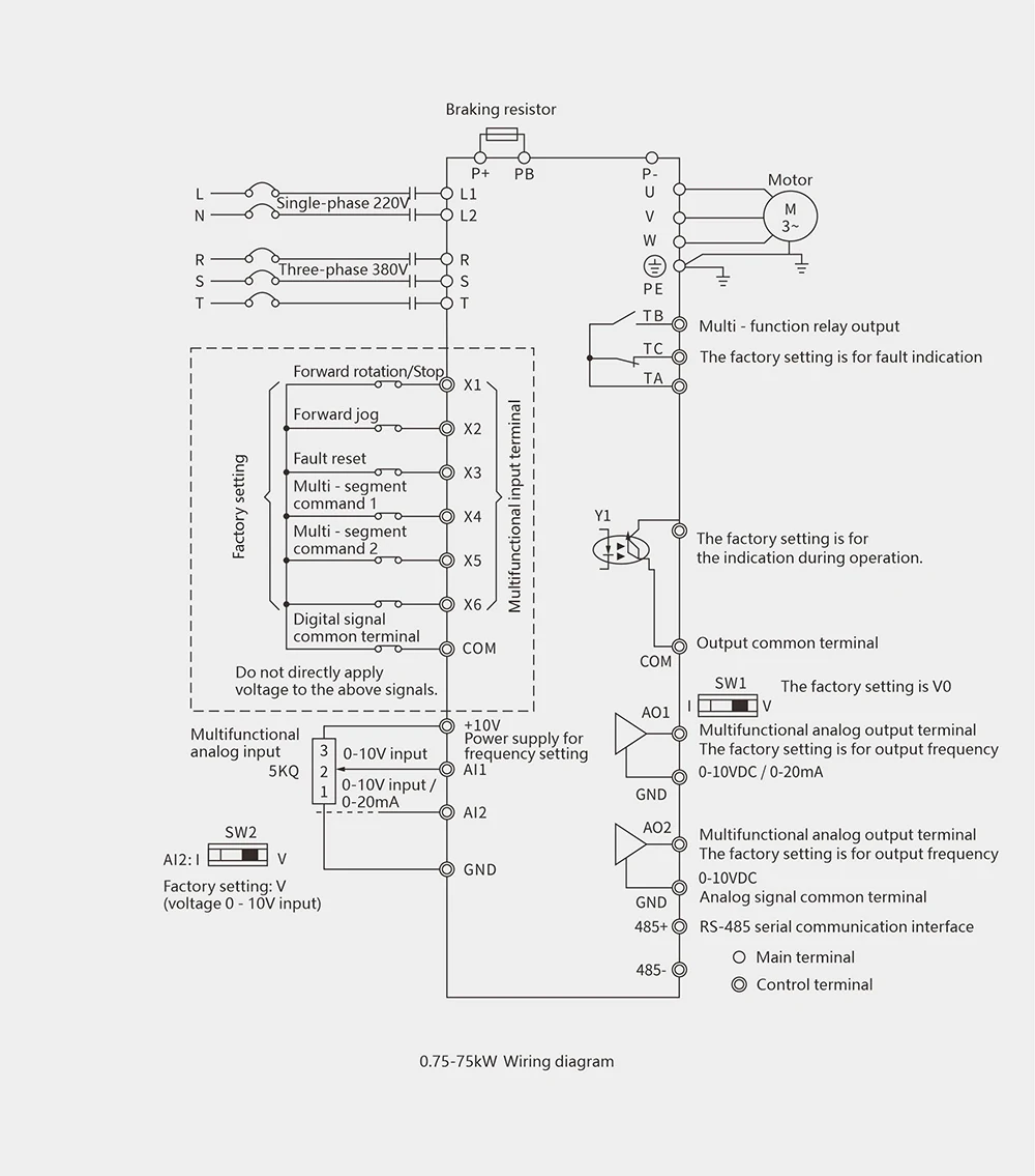 .
Send motor nameplate photos, expected speed range, and whether the load is variable-torque or constant-torque when you ask the supplier to confirm LNC610 versus LNC820 inside the published amp bands.
Frequently Asked Questions
Short answers below; parameter tuning and protection limits stay in the drive manual for your ordered model.
After a VFD is installed, should motor FLA equal the drive’s output current?
Not always. FLA is a nameplate rating at defined conditions; drive output current follows the speed and torque you command and may be lower or briefly higher during events.
Is “motor amp after VFD” the same as input current to the drive?
No. Input current is measured on the line side of the drive and is used for feeder planning; motor-side current relates to FLA and operating point.
Can I size the drive using only the six-amp number on the motor?
Use FLA as one input, but you still need the drive manual’s rated output and input columns and your duty profile—especially if acceleration or overload peaks matter.
Does a lower output current reading mean the motor is always safer thermally?
Not automatically. Low speed on some loads reduces cooling; thermal limits depend on duty, ventilation, and motor design—not one amp snapshot.
Where do branch breaker amps fit after I understand motor vs drive current?
Branch protection uses the drive manual and code practice for the feeder, not motor FLA alone—see the site’s 6 amp 230 V VFD breaker size article for that decision path.
How is this different from a VFD mechanism article?
Mechanism articles explain rectifier, DC link, and inverter stages. This guide compares which amp number belongs in motor, drive output, and line input conversations after installation.
References
External references support current and scope claims in this guide.


