




How vfd works, in practical terms: a variable frequency drive (VFD) adjusts the frequency and coordinated voltage of power delivered to an AC motor, so mechanical speed and torque can follow the process instead of staying locked to line frequency. If you searched how a vfd works, start with that power chain, then compare V/Hz control and vector control (SVC) options against your motor nameplate before you quote a drive.
Browse the Variable Frequency Drive hub when you are ready to compare series and enclosures across the catalog.
 .
What a VFD does in one power-and-speed chain
A VFD sits between the utility or transformer supply and the motor terminals, converting fixed-frequency AC into adjustable-frequency AC. That conversion matters because an induction motor’s synchronous speed rises with supply frequency, so turning frequency down slows the load without gear changes.
The same chain also governs torque because the drive limits magnetizing and working current at each speed point.
When the application only needs a fixed speed, a contactor or soft starter may suffice. When speed must track demand—fans, pumps, or conveyors with varying throughput—the VFD becomes the control point.
| Stage | Physical role | Reader takeaway |
|---|---|---|
| Supply | Feeds the drive with plant voltage | Confirm phase, voltage tolerance, and upstream protection match the drive nameplate |
| VFD power section | Rectifies, stores, and reinverts energy | Expect three functional blocks, not a single “black box” |
| Motor | Converts electrical power to rotation | Match motor class, duty, and cooling to the lowest speed you will run |
Inside the drive: rectifier, DC link, and inverter
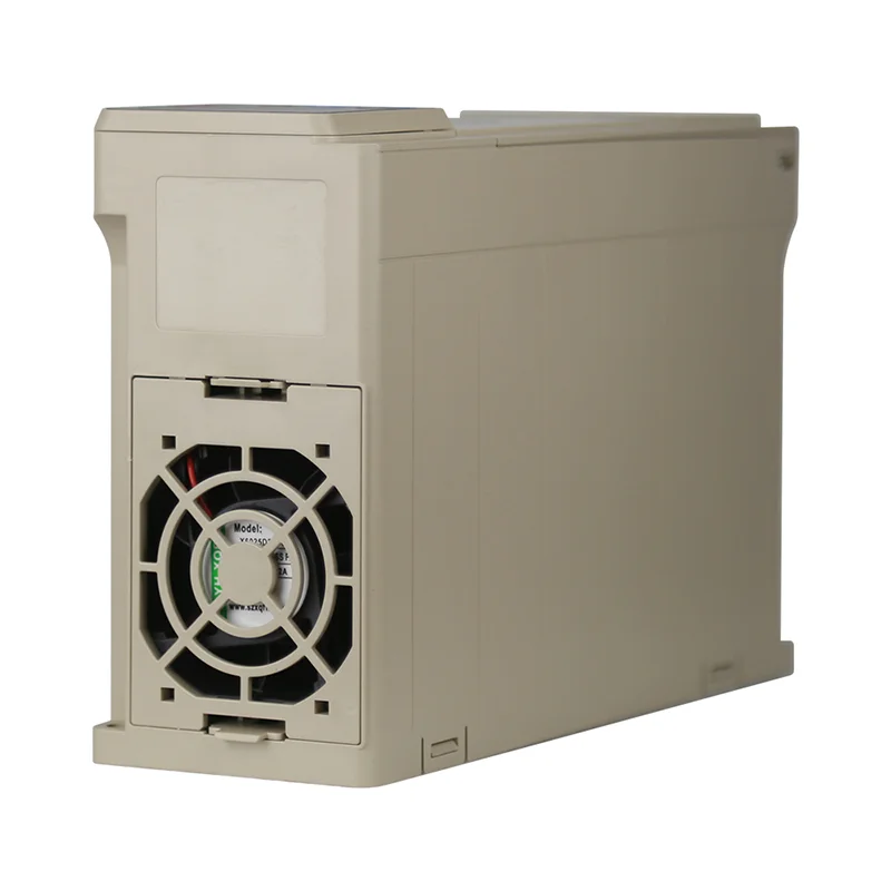
Most general-purpose drives use a voltage-source inverter (VSI) layout: a rectifier converts incoming AC to DC, a capacitor bank forms a stiff DC link, and an inverter switches that DC into pulsed AC that approximates a sine wave at the commanded frequency.
The rectifier is typically a three-phase diode bridge on industrial units, although single-phase input models exist for smaller horsepower. The DC link capacitors smooth ripple and supply energy during fast output transitions. The inverter stage—often IGBT-based—performs high-frequency switching; pulse-width modulation (PWM) determines how those pulses combine at the motor terminals.
Control electronics sit beside the power section. Keypads, discrete inputs, analog signals, and fieldbus commands (Modbus on many catalog drives) set frequency references, acceleration times, and protection limits. None of that logic removes the need for correct motor data; it only executes the reference you provide.
 .
Why changing frequency changes motor speed (and why voltage tracks it)
Induction motors follow the relationship in which synchronous speed increases with frequency and pole count. If you reduce output frequency while holding voltage constant, flux can rise and the motor may overheat. That is why many variable-torque applications use volts-per-hertz (V/Hz) control: voltage falls roughly in proportion to frequency so magnetic flux stays in a usable range.
For a US nameplate example (460 V, 60 Hz motor class), the illustrative ratio is about 7.67 V/Hz. Your actual drive must be programmed for the motor nameplate and the lowest continuous speed you expect. Field weakening above base speed is a separate operating region; the following sections stay with the common zero-to-base-speed range used in fan and pump retrofits.
When load inertia is high, acceleration and deceleration ramps limit inrush and prevent overvoltage on the DC bus. If regeneration is possible, braking resistors or active front ends may be required—topics that belong in the project electrical design, not in a catalog assumption.
Control modes buyers actually see: V/f, vector, and PID
Catalog sheets list control modes because the same hardware can behave differently depending on firmware settings. V/Hz (scalar) control is straightforward for pumps and fans where the load torque rises with speed. Open-loop vector control—sometimes labeled sensorless vector (SVC)—attempts tighter torque response without a encoder, subject to the drive’s auto-tuning and motor data quality.
Process loops add another layer. Built-in PID blocks let a drive hold pressure or flow by adjusting its own speed reference when wired to a transducer. Whether PID belongs in the drive or in a PLC is an architecture choice; many general-purpose lines still expose a PID block for simple loops.
| Mode (typical label) | What it optimizes | When buyers shortlist it |
|---|---|---|
| V/Hz | Simple flux versus speed | Fans, pumps, lightly loaded conveyors |
| Vector / SVC | Torque response without encoder feedback | Hoists, extruders, tighter dynamic loads |
| PID | Closed-loop process variable | Constant pressure or flow with onboard sensing |
Where VFDs pay off—and where a soft starter or fixed speed may fit
Adjustable-speed drives earn their place when the process benefits from running below line speed for long periods. Department of Energy (US) material on adjustable-speed drives emphasizes matching motor speed to load requirements, especially in fan and pump systems where power demand drops when speed drops.
That does not mean every motor should receive a VFD. A soft starter reduces inrush and mechanical shock but leaves the motor at full synchronous speed once the start finishes. Fixed-speed contactors remain valid when the equipment always runs at one speed and tuning a drive would add cost without benefit.
 .
Commissioning checks before you treat catalog text as project proof
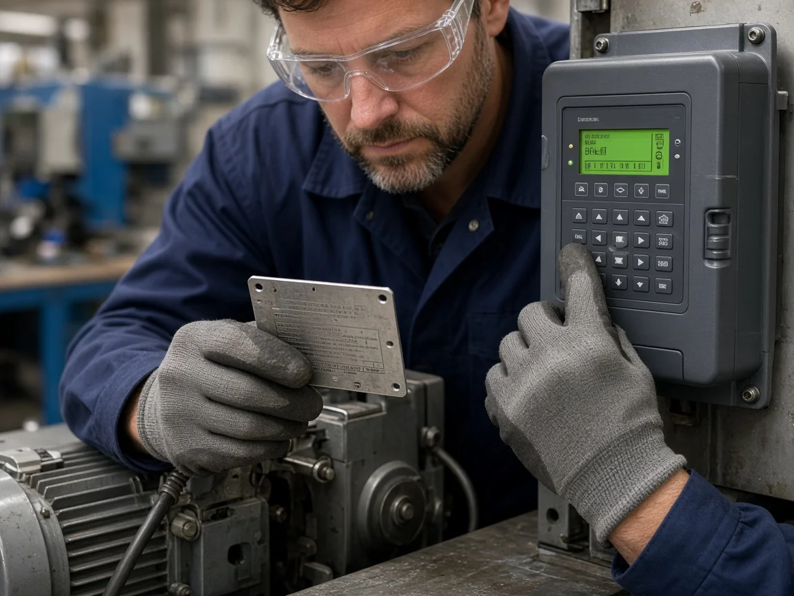
Commissioning begins with documents, not defaults. Collect the motor nameplate (voltage, frequency, full-load amps, insulation class), verify supply phase against the drive input rating, and confirm grounding and cable routing follow the manufacturer’s install guide for the ordered model.
Important: Community discussions and field questions repeatedly return to whether “any motor” can run from a spare drive. Nameplate data, inverter-duty expectations, and cable length limits still govern the answer—swap the drive only after those items match the application record.
Check braking needs before you assume internal brake choppers exist. Some series ship without braking units as standard; braking must be specified when regenerative energy or fast deceleration could trip overvoltage faults. Communication settings—Modbus address, baud, and register map—should be captured in the same commissioning sheet so PLC integrators inherit a single source of truth.
Matching a general-purpose drive to your machine (LNC610 as a bounded example)
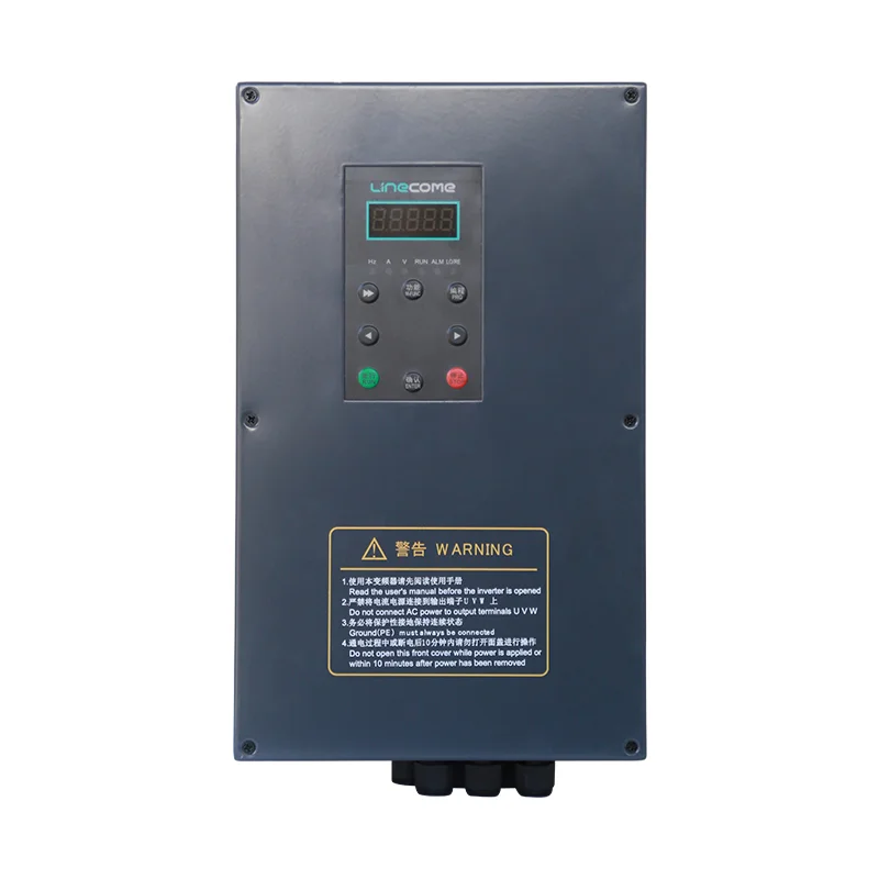
After the mechanism sections, a concrete catalog example helps procurement without turning the article into a datasheet paste. The public LNC610 general-purpose VFD series page lists V/F control and open-loop vector (SVC) among basic functions, documents Modbus, and shows an output frequency range of 0–500 Hz in the specifications table for the series.
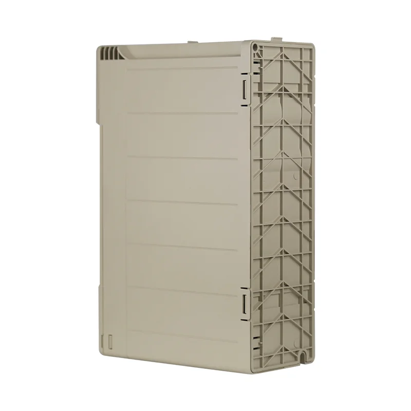
Those statements apply to the published LNC610 family page, not to every imaginable retrofit. You still must select the exact model row for input voltage, output current, and enclosure, then confirm braking, EMC filtering, and motor cable length against the manual for that SKU.
| Public LNC610 page item | Why it matters on the shop floor | Your project still must verify |
|---|---|---|
| 0–500 Hz output frequency range | Shows how far the series can command speed electronically | Continuous torque available at low speed, motor cooling, mechanical limits |
| V/F and SVC modes | Links earlier control-mode section to a real catalog | Auto-tune quality, motor data entry, load inertia |
| Modbus on overview copy | Shows integration path for SCADA/PLC | Register map, baud, isolation, fault handling |
 .
When the LNC610 series fits the duty described above, continue specification on the product page and share motor nameplate photos with the supplier if you need a model row confirmation. If the application only needs a controlled start at one speed, compare soft-start alternatives in the VFD hub before you commit to full variable-frequency control.
Frequently Asked Questions
Short answers here cover motor compatibility, energy expectations, and the inverter naming mix-up that still appears on job sites.
How does a VFD work on a motor?
It supplies adjustable-frequency AC so the motor’s operating speed follows the commanded frequency while the drive regulates voltage (often through V/Hz or vector methods) to keep torque usable.
What are the three main parts of a VFD?
The power section is usually described as a rectifier, DC link capacitors, and an inverter that reconstructs AC output.
Can any motor run on a VFD?
Only after you match nameplate voltage, frequency, current, duty, and cooling to the drive ratings and program the drive with correct motor data; inverter-duty motors may be specified for demanding low-speed runs.
How does a VFD control speed?
The drive changes output frequency (and associated voltage) rather than relying on mechanical gearing; ramps control how quickly frequency changes.
What is the difference between V/Hz and vector control?
V/Hz holds a approximate voltage-to-frequency ratio for simpler loads, while vector-style control attempts tighter torque control using a motor model and drive-side measurements.
Does a VFD always save energy?
Not automatically. Energy reductions appear when the load needs less speed or torque for long periods—common in throttled fan and pump scenarios—not when the motor would run at full speed anyway.
Why do people call a VFD an inverter?
Colloquial usage treats the entire drive as an “inverter” even though the inverter is technically only the output stage; naming threads in community sources highlight the same confusion.
References
Related practical guides
For practical checks after selecting a drive, see our guides to motor overheating at low VFD speed and VFD PID control for constant-pressure pumps.


