




VFD DC injection braking applies a controlled DC current to a compatible motor to help bring rotation to a stop. Its usefulness depends on the motor, load, starting speed and permitted heating. Before enabling it, confirm that the exact drive supports the function and that the motor manufacturer accepts the intended duty. A shorter stopping time is useful only when the complete machine remains within its mechanical and thermal limits. DC injection must not be treated as an automatic substitute for a mechanical holding brake, a safety stopping function or electrical isolation.
This guide covers selection and acceptance questions for an induction-motor installation. It does not provide universal current percentages, parameter numbers or brake durations. Those values must come from the supplied drive and motor documentation, followed by an approved commissioning procedure.
Separate three different stopping jobs
A normal deceleration ramp asks the drive to reduce motor speed over time. Depending on the load, the motor can return energy toward the drive’s DC bus. The available braking arrangement and bus protection determine whether the requested ramp can actually be achieved. The time entered on the keypad is therefore a command, not proof of the measured machine stopping time.
DC injection produces a stationary magnetic field instead of the rotating field used for ordinary operation. Rotation through that field produces braking action. The method adds heat to the motor and depends on the drive being able to deliver the commanded current. It should be evaluated as a specific operating mode with its own permissions and limits.
A mechanical brake provides a separate physical function. Holding a suspended or externally driven load requires an engineered arrangement suited to that load. Do not infer holding capability from a drive display showing zero frequency. The distinction matters when air flow, back pressure or gravity can move a machine after its electrical stop sequence ends.
For the energy path through a resistor, see the separate guide to VFD braking resistor sizing. Increasing DC injection time does not increase an installed resistor’s duty rating, and adding a resistor does not by itself establish a DC injection setting.
Start with an application record
List the driven equipment, motor identification, normal speed range and the circumstances that require stopping. Include whether the load can coast freely, continue driving the shaft or reverse direction. A fan being driven by moving air presents a different starting condition from a stationary unloaded motor on a test bench.
Record the expected operating pattern as well as a single stop. Include normal stops per shift, closely spaced stops during setup, possible aborted starts and the interval available for cooling. A successful cold demonstration does not establish that repeated operation is acceptable. The person approving the duty needs a realistic sequence rather than only a maximum speed and one desired stop time.
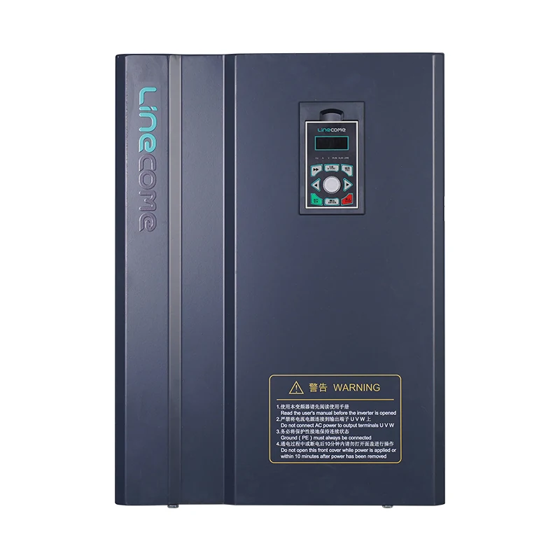
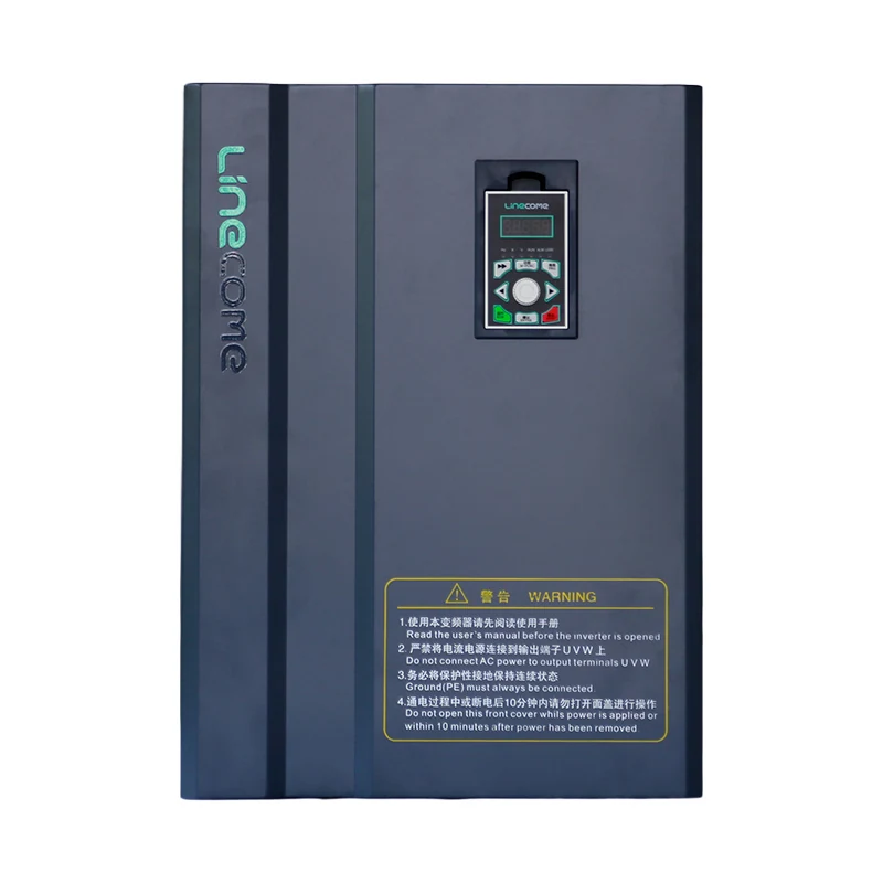
The LNC860S vector VFD product page identifies a real LINECOME drive family for project discussions. Request the exact supplied frame’s manual and firmware details before specifying DC injection. Product photographs and general descriptions do not prove that a particular parameter, motor type or stopping duty is supported.
Confirm the electrical and motor boundaries
Check the motor type first. A procedure written for an induction motor should not be transferred to a permanent-magnet motor without explicit approval. Confirm the connected motor current, voltage connection and protection configuration. Incorrect motor data can undermine the interpretation of current limits and thermal protection before the braking question is even considered.
Review every component between the drive and motor, including contactors, filters, reactors and any special interface equipment. Obtain confirmation that the complete output arrangement permits the intended mode. An output circuit that works during normal running is not automatically approved for every braking sequence.
Keep the drive output connected or disconnected only as the supplied instructions permit. Coordinate the sequence with the existing VFD output contactor interlocks. Opening a contactor while the drive is actively delivering braking current must not become an improvised way to end braking. The command sequence and proof of the resulting state should be documented together.
Compare the choices before changing a parameter
The following table is a planning aid. It describes questions to resolve, not approval of a particular machine or drive. Keep the selected method consistent with the motor manual, the machine risk assessment and the required stopping behavior.
| Requirement or observation | Question to resolve | Evidence to retain |
|---|---|---|
| Motor coasts beyond the required stop point | Can an approved ramp meet the requirement, or is another braking method needed? | Measured speed or motion trace and approved acceptance limit |
| Low-speed rotation persists near the end of a stop | Does the exact drive permit DC injection at that stage? | Manual section, enabled condition and measured result |
| Frequent short operating cycles | Can the motor tolerate the repeated electrical and braking heat? | Duty sequence, temperature trend and manufacturer review |
| Shaft must remain stationary after stopping | What independent holding arrangement is required? | Brake specification, feedback and machine-level verification |
| Supply power is lost | What stopping or holding behavior remains available? | Power-loss analysis and controlled test record |
| Maintenance requires access | How are all hazardous energy sources isolated? | Equipment-specific isolation procedure and verification |
For the last row, CCOHS guidance on lockout distinguishes control functions from the physical isolation needed for maintenance. WorkSafeBC’s lockout guidance likewise places energy isolation in the main power path. These resources explain safety boundaries; they do not supply braking settings for a LINECOME drive.
Review current, duration and entry conditions together
A DC braking setup normally involves more than one decision: when the mode may begin, the requested current and how long it may remain active. Some drives have separate functions around starting and stopping. Confirm the actual definitions rather than assuming that similarly named parameters have the same meaning across manufacturers.
The engineer should identify the permitted entry speed or frequency, the current basis and the conditions that terminate the mode. A percentage can refer to a defined current base that differs between products. Record that base explicitly. A copied number without its definition is not a usable setting, even if another installation appears mechanically similar.
Do not invent a universal starting percentage or extend duration until a troublesome load finally stops. If the required braking performance falls outside the permitted motor duty, reconsider the method. A practical design review may lead to a different stop strategy, a suitable brake or a revised process sequence rather than a more aggressive parameter.
Make motor heating visible during acceptance
Ask how motor temperature is being assessed and what limits apply. Where suitable sensors are provided, record their interpretation and how they interact with the control system. A drive’s estimated thermal state and an external motor sensor are different sources of evidence; neither should be silently substituted for the other.
Account for cooling conditions during low-speed operation and standstill. The motor’s ability to shed heat can differ from its behavior at normal running speed. Include starting and running losses in the review instead of assigning the entire thermal budget to the braking interval alone.
For troubleshooting around operating speed and cooling, use the complementary guide to motor overheating at low speed. The present decision is narrower: whether a specified DC braking duty remains acceptable through the complete sequence. Retain the observed temperature trend, surrounding conditions and recovery interval so the result can be repeated later.
Test the sequence under controlled conditions
Qualified personnel should establish the test boundary, instrumentation and means of preventing unexpected movement before making changes. Preserve the original parameters and define an immediate stop condition for the test. Keep guards, access restrictions and mechanical restraints consistent with the approved procedure.
First prove the ordinary run and stop behavior without attributing every change to DC injection. Record the stop command, drive state, actual shaft or machine movement and any fault indication on a common timeline. Electrical frequency alone is not a direct measurement of rotor position or confirmed standstill.
Where the manufacturer allows adjustment, change one approved setting at a time and compare the complete trace. Repeat at the operating conditions specified for acceptance, including the relevant load and starting motion. If a fault, unexpected movement or unacceptable heating occurs, preserve the evidence and resolve it before expanding the test.
Before returning the machine to service, restore any temporary forces or test overrides, check the final parameter set against the approved record and confirm the intended restart permission. A stop that appears successful can still leave a dangerous automatic restart path when a maintained run command remains active.
Plan for power loss, faults and restart
Ask what happens when the DC bus can no longer supply the braking mode, the drive faults or the control command disappears. These are separate cases from a normal stop with all supplies healthy. The machine design must address the resulting movement rather than assuming that the normal electrical sequence remains available.
Where a mechanical brake is fitted, define how its command, position feedback and release permission relate to the drive state. A timing delay alone does not prove that the brake actually applied. Review failures in the feedback path as well as failures in the command path.
For an overview of the drive’s normal conversion stages, the RealPars video below explains the equipment behind the stopping discussion. It is background education rather than a DC injection setup tutorial. Use the exact drive manual for application-specific parameters and permissions.
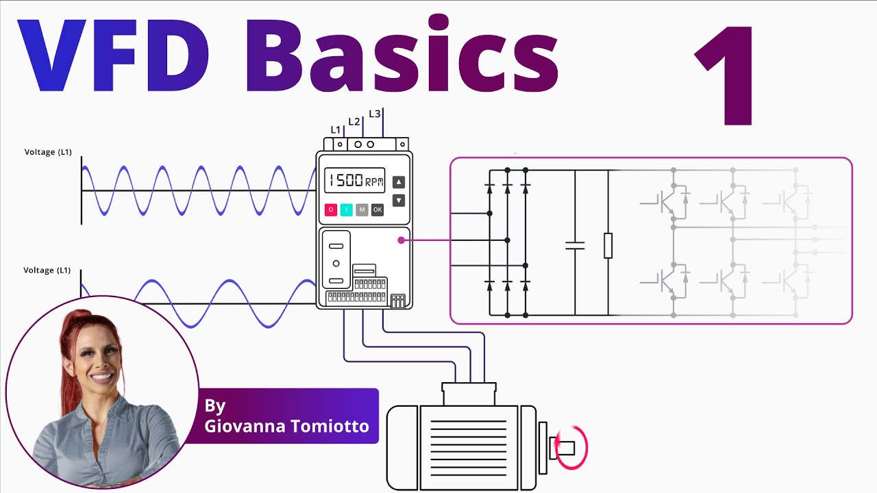
Video by RealPars. Watch Variable Frequency Drives Explained | VFD Basics – Part 1 on YouTube.
Send a complete inquiry instead of a stopping-time request
Provide LINECOME with the motor nameplate, exact drive model, supply information, load description and existing circuit drawing. State the normal operating speed, measured coast-down behavior, required stop condition and expected number of stops. Identify any external force that can continue moving the shaft after the process stop.
Also include existing output accessories, the proposed motor-temperature monitoring, brake details where applicable and the required behavior after supply restoration. Ask for written confirmation of function availability and the permitted application boundaries. Separate the evidence needed for product selection from the tests needed for final machine acceptance.
The most useful handover record contains the approved settings, manual revision, measured stopping trace, temperature observations and unresolved limitations. That record lets a later replacement or maintenance visit begin with verified facts rather than an unexplained keypad number.
Frequently asked questions
Is DC injection braking the same as a braking resistor?
No. DC injection applies current to the motor for a specific braking mode, while a braking resistor is part of an arrangement that dissipates energy from the drive’s DC bus. Their settings, limits and application checks are different.
Can DC injection replace a mechanical holding brake?
Do not assume it can. Holding requirements must be assessed for the actual load, including supply loss and drive faults. Use an independently engineered holding arrangement wherever the application requires it.
What current and time should I enter?
Use values approved for the exact drive, motor and operating duty. Confirm the current base, entry conditions and thermal limits, then verify the complete stopping sequence. There is no universal percentage or duration suitable for every installation.


