




PLC relay output suppression should be selected for the actual inductive load, its AC or DC supply, the output module’s switching limits and the required release time. A suppression component can reduce the transient created when a coil is switched off, but it can also change how quickly a relay, contactor or solenoid releases. Start with the exact output-module and load documents, then confirm the complete circuit by inspection and a controlled timing test. Do not select a diode, resistor-capacitor network or voltage clamp from the PLC’s nominal supply voltage alone.
This guide focuses on specifying and accepting an inductive output circuit in an industrial cabinet. It does not assign universal component values or replace the module manufacturer’s wiring instructions.
Identify the switching device before choosing protection
An output label in the PLC program describes a logical command. It does not establish whether the physical output is an electromechanical relay, a transistor or another switching device. The model of the installed output module is the starting point for the hardware review.
For a relay output, obtain the contact ratings that apply to the actual load and switching duty. A prominent resistive-load current rating is not automatically the allowed inductive-load switching rating. Also check common-group limits and any restrictions on combining supply circuits within the module.
For a transistor output, the module’s polarity, internal protection and permitted external suppression matter. Do not transfer the relay-output circuit to a transistor channel without reviewing those differences. An interposing relay introduces another coil and another set of contacts, so it changes the drawing rather than removing the need for a protection assessment.
The PLC control cabinet for industrial automation is a relevant enclosure and integration reference. Its external photograph does not identify the installed output modules or demonstrate that a particular coil, suppressor or safety function is included. Ask for the project-specific bill of materials and circuit schedule.
Understand the turn-off event
An energized coil stores magnetic energy. When the switching path opens, the circuit must deal with that energy. A suppression network controls the resulting electrical transient, while the load’s mechanical behavior determines when the associated contacts or actuator actually return.
The Institution of Electronics guide to inductive-load suppression distinguishes DC diode suppression from AC-compatible suppression approaches and discusses the turn-off tradeoff. The practical consequence is that “less electrical noise” and “fast enough mechanical release” need separate acceptance checks.
For switching-design context, Texas Instruments’ inductive-load application brief examines clamp behavior and current decay. Its semiconductor examples explain the principle; they are not a component selection for an unspecified PLC module or evidence of a feature in a LINECOME cabinet.
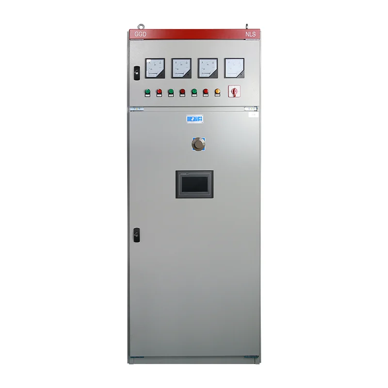
The industrial PLC cabinet above is another website product reference. Use the project documentation to identify where output modules, interposing relays and terminal groups belong. The cabinet exterior cannot verify the protection fitted inside it.
Match the suppression approach to the load
Use the table as a review agenda with the module and coil supplier. It lists decisions that require confirmation, not interchangeable prescriptions or universal wiring positions.
| Circuit condition | Suppression question | Acceptance evidence |
|---|---|---|
| DC relay or solenoid coil | Is a diode or another approved clamp suitable for the required release behavior? | Coil voltage, polarity, energy duty and timing data |
| AC coil | Which AC-compatible suppression accessory is approved? | Coil supplier’s RC or varistor accessory specification |
| Fast release required | Does the chosen clamp change dropout beyond the process limit? | Measured command-to-feedback or actuator timing |
| Built-in coil suppressor | What protection is already present? | Exact coil/accessory part number and internal circuit information |
| Interposing relay installed | Are both its coil and its switched load addressed? | Complete drawing showing the two separate circuits |
| Several outputs share a common | Can the module and supply support the combined duty? | Group ratings and simultaneous-operation assessment |
A conventional flyback diode is a DC approach and must have the correct orientation for its intended circuit. Do not place an ordinary diode across an AC coil as though the two applications were equivalent. Obtain approved component and installation details before assembly.
For the module itself, the supplier must define the applicable limits. The table deliberately avoids a generic capacitance, resistance, clamp voltage or current multiplier because those numbers require load and device information that a cabinet photograph cannot provide.
Keep the coil circuit and contact circuit distinct
When a PLC drives an interposing relay, there are two switching problems to consider. The PLC output energizes the relay coil. The relay contacts then switch a separate load. Protection that suits the first circuit does not automatically protect or rate the second circuit.
Draw both sides with their own supply references and component identifiers. Record the voltage and load type on each side. This prevents a maintenance technician from assuming that every wire associated with a low-voltage coil is at that same voltage.
If the relay contacts feed a contactor coil, identify that coil’s approved suppression accessory too. If they feed a different type of load, review the corresponding switching duty. Replacing a relay with a higher headline current rating may still leave the actual load category or release behavior unresolved.
The PLC cabinet overview explains the broader assembly. For this output-specific task, require a channel list that connects the software address to the module terminal, interposing device, field terminal and final actuator. That traceability is more useful during acceptance than a list of unconnected component names.
Check an existing circuit before adding another suppressor
Read the load and accessory part numbers. A contactor coil plug, relay socket module or solenoid connector may already contain suppression or an indicator circuit. Record exactly what is fitted rather than relying on the appearance of an LED.
Compare the installed accessory with the approved drawing. If the drawing shows one type but the cabinet contains another, resolve the substitution before judging its performance. Adding another device without understanding the original circuit can make both documentation and fault diagnosis more difficult.
Also inspect the intended installation location. Ask the designer to specify the connection points and routing in the controlled drawing. A statement such as “fit near the output” does not clearly identify whether the accessory belongs at the module, an interposing relay or the field coil.
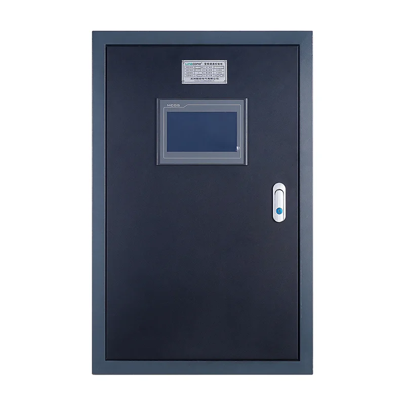
The PLC cabinet shown above illustrates another enclosure arrangement in the same product line. It is not a photograph of a suppression retrofit or evidence of tested noise performance. The accepted drawing and inspection record must establish the actual circuit.
Verify release timing as an independent result
Agree on the required response before testing. Define the start event, such as the physical output changing state, and the end event, such as auxiliary feedback changing or a valve reaching its specified condition. A software timestamp alone may not capture the complete mechanical response.
Record the module, load and suppression part numbers alongside the timing result. Include the operating conditions that matter to the application and the test method’s resolution. A number with no component identity or event definition is difficult to compare after a future replacement.
Consider an illustrative process in which a PLC turns off a solenoid and then enables the next action after feedback confirms release. If a new coil accessory changes the release behavior, the electrical output may be working correctly while the sequence responds differently. Review the measured event chain rather than blaming the program immediately.
This example provides no universal delay or permission to shorten a timer. The acceptable response belongs to the machine’s process and safety design. For safety-related functions, changes require the applicable validation; a general-purpose output test is not a substitute.
Distinguish suppression faults from other symptoms
A channel that commands correctly but does not move the load needs a wider diagnosis. Check the supply path, protective device, terminal identification, module indication, load condition and feedback logic using the approved procedure. Suppression is one part of that circuit, not the explanation for every failure.
A relay contact that remains closed may involve damage, wiring, an unintended parallel path or an incorrect observation point. Preserve the failed component and operating history where useful. Do not repeatedly cycle a damaged output as the default recovery method.
Likewise, input disturbances after a load switches need measured evidence. A suppression review can be relevant, but so can supply drop, routing, bonding or input compatibility. The sinking and sourcing input checklist addresses the input side. Keep its compatibility assessment distinct from the output protection review so the investigation does not change several unrelated things at once.
Inspect and test with a defined safe procedure
Have qualified personnel isolate and verify the circuit before changing wiring. Account for separately supplied field loads and any other energy sources. HSE guidance on work on electrical equipment emphasizes planned work, secure isolation and competent personnel.
For any necessary energized measurement, use an approved test plan, suitable equipment and the required protective measures. This article does not instruct a reader to probe an exposed output or connect a general-purpose oscilloscope to an unknown circuit.
After a change, verify normal operation, output-off behavior and the relevant feedback sequence. Where restart prevention is involved, use the emergency-stop reset acceptance guide as a related planning resource. Changing coil release behavior should never be treated as evidence that the complete stop or restart function has been validated.
Information to include in a cabinet RFQ
Provide the PLC and output-module models, number of channels, supply arrangement and simultaneous switching duty. List every controlled load with its coil voltage, AC or DC type, exact part number and switching frequency. Identify existing suppressors and the required response of the driven mechanism.
Ask the supplier for applicable contact or output limits, the proposed interface arrangement and approved accessories. Require the circuit diagram to show the actual connection points, component identifiers and common groups. Clarify who verifies field-device compatibility if the actuator is supplied by another company.
At acceptance, retain the as-built circuit, installed-part photographs, functional and timing results, and any replacement restrictions. This gives maintenance a usable reference when a coil or output module fails later. The most useful handover record connects the selected protection to the load and the measured response, instead of simply stating that suppression was installed.
Video: the relay system behind the output circuit
The RealPars lesson below explains electromagnetic relays and their use in control systems. It provides background for distinguishing a coil from the contacts it operates. The component selection and release-time checks remain those in the project documents and this checklist.
Video by RealPars. Watch What is a Relay System ? on YouTube.
Frequently asked questions
Can I fit the same diode to every PLC-controlled coil?
No. First confirm whether the coil is AC or DC, what suppression is already present, what the output permits and how quickly the mechanism must release. Use the approved circuit and accessory data for the actual load.
Does an interposing relay remove the need for suppression checks?
No. It creates a coil circuit driven by the PLC and a contact circuit switching another load. Review each circuit separately, including the load duty and any approved suppression on either side.
Is correct PLC output indication enough for acceptance?
No. An indication confirms only part of the command path. Acceptance should also establish the actual load operation, output-off response, feedback and required timing under the defined test conditions.


