




A DC circuit breaker polarity check must establish the permitted current direction through each pole, the approved source and load connections, and whether the circuit can feed a fault from either side. A familiar housing, an ampere label or a successful continuity test cannot answer those questions. Before specifying or reconnecting a breaker, obtain the exact device diagram and compare it with the actual DC source arrangement. Where the installation can charge and discharge through the same path, ask for explicit confirmation of suitability for that duty rather than assuming every DC breaker is bidirectional.
This guide is a document and acceptance checklist for industrial buyers and panel engineers. It does not provide a universal terminal wiring diagram. Product markings and the instructions for the delivered device take precedence over examples from another breaker family.
Why polarity needs its own selection check
Overcurrent detection and interruption are separate issues. A device may carry normal current in an arrangement that is unsuitable when its contacts must interrupt a fault. This is why testing whether equipment powers up is insufficient evidence of correct breaker selection.
The IRENA-hosted training presentation on grid-connected PV installation illustrates polarized breaker arrangements and emphasizes the current direction through the device. Its examples are useful for understanding the distinction between physical mounting and electrical direction. They are historical training material, not a current approval for a new solar installation or a terminal schedule for a different product.
For a quotation involving the WSB6Z DC miniature circuit breaker, request the current technical sheet, wiring diagram and application confirmation. The website photograph identifies the product family for the discussion; it does not establish an unlisted voltage, interrupting rating, reverse-feed approval or certification.
Separate four questions that often get mixed together
First, identify the polarity of the conductors in the system. Positive, negative and an earthed conductor describe the circuit arrangement. They do not automatically explain every symbol printed beside a breaker’s terminals.
Second, establish normal current direction. A supply feeding a load has one operating condition; a battery connected to a charger and inverter may have several. Show these operating states on the system drawing rather than reducing the discussion to the location of a battery symbol.
Third, identify where fault energy can originate. A downstream energy-storage device can change the fault-source picture even when normal operation appears simple. The responsible designer should review each source and the fault locations it can feed.
Fourth, obtain the device’s approved connection. This includes terminal designations, required pole links, line/load restrictions and any direction limits. Treat the complete diagram as one configuration. Selecting a convenient detail from several unrelated diagrams can produce an arrangement that none of their manufacturers approved.
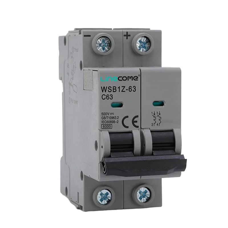
The related WSB1Z DC device above is another product reference for comparing the information needed in a supplier submission. Its photograph is not proof that its terminal rules match those of the featured WSB6Z family.
Build an operating-state matrix before choosing terminals
Use a short matrix to make hidden assumptions visible. The following table lists questions to resolve; it deliberately supplies no universal polarity assignment or wiring instruction.
| Operating state | Information to put on the system drawing | Evidence needed before acceptance |
|---|---|---|
| One supply feeding one load | Source location, maximum operating voltage and load branch | Exact breaker diagram and DC ratings for that arrangement |
| Battery charging | Charger path, battery path and current direction | Confirmation that the selected connection covers charging duty |
| Battery discharging | Inverter or load path and possible reverse direction | Explicit suitability for both operating directions where applicable |
| Parallel sources | Each source contribution and disconnect location | Fault assessment covering every contributing source |
| Earth fault | Earthing arrangement and affected conductors | Protection design for the actual system, not just pole count |
| Maintenance isolation | All possible backfeed paths | Approved isolation procedure and device suitability for isolation |
The European research project SHIFT2DC’s DC protection systems design report discusses direction-sensitive protection and DC interruption characteristics. Its engineering analysis supports checking reverse current and the complete DC circuit. It does not approve a particular LINECOME product. Device selection still requires the relevant manufacturer’s ratings and an installation-specific protection design.
For control-panel integration, keep this matrix beside the motor control panel protection RFQ checklist. The DC branch and motor power branch require their own evidence; an accepted AC motor protection arrangement cannot be transferred automatically to a DC auxiliary circuit.
Read the delivered device, not a catalogue thumbnail
Record the model, pole count and all suffixes from the actual unit. Take clear photographs of the front, terminal markings and side diagram before the product is hidden by wiring. Attach the corresponding document revision to the purchase record.
Ask the supplier to identify which symbols describe the circuit and which describe a restriction on the device. If the explanation depends on a page that is not included in the submission, request that page. An email saying “DC compatible” is too broad to resolve a specific terminal arrangement.
Also distinguish operating voltage from interruption capability. A marking associated with insulation is not automatically the allowed operating voltage for every pole connection. Likewise, a quoted breaking value needs its applicable voltage and configuration. Request the complete rating statement instead of comparing isolated numbers from two quotations.
Have the designer mark the accepted connections on the project drawing and give that drawing a revision. This provides a stable reference for the assembler, inspector and maintenance team. A loose annotated product photograph can be useful supporting evidence, but it should not be the only controlled instruction.
Why an AC breaker photograph is included
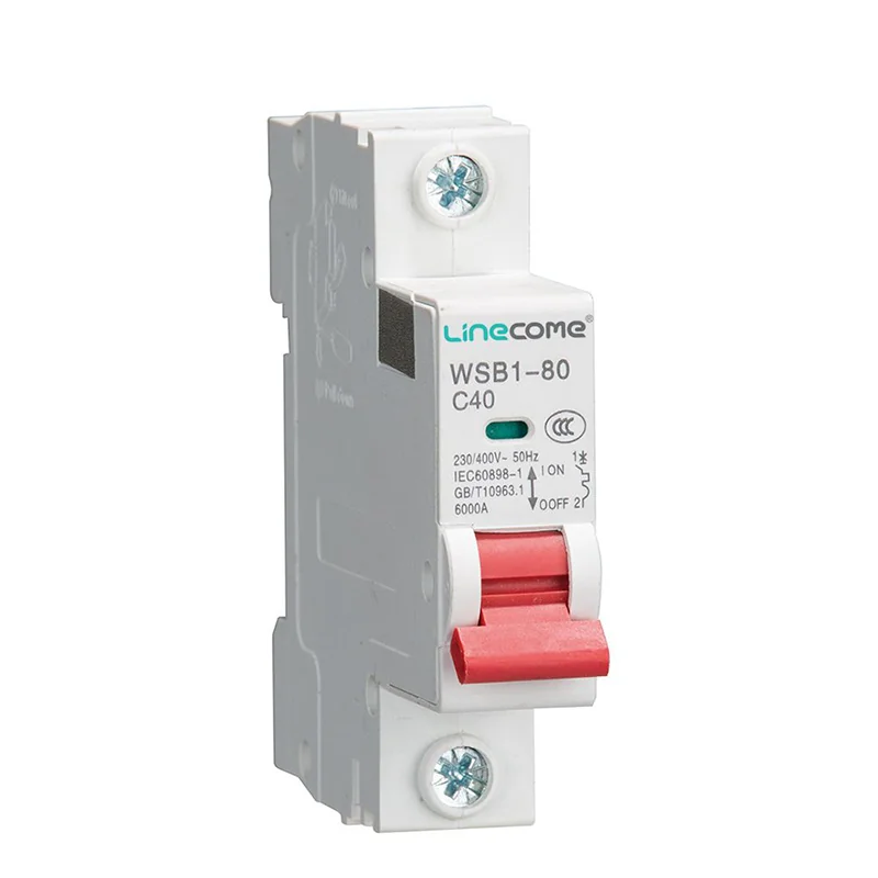
The WSB1 AC miniature circuit breaker above illustrates a separate catalogue category. Similar handles, dimensions or mounting methods do not establish that an AC device has the required DC rating. It is included as a purchasing comparison, not as a substitute for the DC breakers discussed here.
When a supplier proposes an alternative, compare its application documents before comparing price. Check the complete model, DC operating voltage, protection characteristic, interruption conditions, wiring requirements and applicable approvals. A visually similar replacement may require a different arrangement or may be unsuitable for the circuit altogether.
Avoid using a generic statement that series poles increase voltage capability as a wiring instruction. Pole connections are device-specific. The project designer needs the approved arrangement and its ratings, including what happens under the relevant earth-fault conditions. A larger pole count alone does not settle the issue.
Inspection without a destructive fault experiment
Separate document review, deenergized inspection and controlled functional checks. The acceptance plan should state what each stage can demonstrate and what it cannot. This prevents a basic operational test from being recorded as proof of short-circuit interruption performance.
During document review, compare the source matrix with the supplier’s confirmed application. During deenergized inspection, the qualified team can compare installed conductor identification, terminal positions and pole links with the approved drawing. Changes should be resolved on the drawing before the cabinet is released.
A controlled operational check may demonstrate that the intended load receives power and that an approved switching sequence works. It does not reproduce a rated fault test. Do not create an intentional short circuit to see whether a breaker trips. Where verification of protection performance is needed, use the specified engineering and test process with suitable equipment and competent personnel.
HSE guidance on working on electrical equipment emphasizes planned work, secure isolation and competent personnel. The inspection procedure must account for batteries and other backfeed sources, not only the main incoming disconnect.
An example of a quotation that needs clarification
Suppose a request says “DC breaker for a battery-fed control cabinet” and supplies only nominal voltage and normal load current. That description leaves open whether the branch can also carry charging current, whether another source can energize it, and which conductors are earthed. Quoting immediately may hide an important application assumption.
A better response attaches a small system diagram and asks the designer to confirm the operating states. The supplier then identifies the exact proposed breaker and documents its permitted connection. If the application includes current reversal, that condition appears explicitly in the approval request and response.
This example contains no assumed rating or recommended terminal arrangement. Its purpose is to improve the information exchanged before selection. If the resulting documents still disagree, hold that branch from release and obtain a corrected selection rather than asking an assembler to interpret ambiguous markings.
For a solar-pump system, coordinate this work with the dry-run protection commissioning guide. Pump process protection and electrical fault protection solve different problems. For a cabinet’s auxiliary supply, the 24V voltage-drop checklist helps examine load-side performance after the protective arrangement has been approved.
What to put in the purchase and handover package
Send the supplier the system drawing, maximum relevant DC voltage, expected load duty, source information, earthing arrangement and environmental conditions. State whether charging, discharge, regeneration or alternative supplies are possible. Ask the electrical designer to provide the fault assessment needed for the selection.
Request the exact part number, current technical documents, approved terminal arrangement, applicable ratings and any required accessories. Clarify whether isolation duty is required and supported. Keep commercial substitutions subject to the same review rather than accepting “equivalent” as a complete technical explanation.
At handover, retain the accepted drawing revision, photographs of installed markings, inspection record and the supplier’s written clarifications. Include a maintenance instruction that replacement breakers must be checked against this package. That makes later replacement a repeatable review instead of a fresh guess based on appearance.
Video: how a breaker interrupts a circuit
The RealPars lesson below explains the operating mechanisms inside a miniature breaker and introduces arc interruption. Use it to understand why interruption matters. It is not a DC polarity wiring tutorial and does not qualify the illustrated mechanism for any particular DC installation.
Video by RealPars. Watch Circuit Breaker Explained | Working Principle on YouTube.
Frequently asked questions
Does every DC circuit breaker have polarity restrictions?
No universal rule applies to every family. Check the exact device documents for direction sensitivity, line/load restrictions and approved connections. Absence of an obvious symbol in a website photograph is insufficient evidence that the delivered unit supports either current direction.
Does a continuity test prove correct DC breaker polarity?
No. Continuity describes a closed conductive path under the test conditions. It does not demonstrate rated interruption capability, compliance with the approved pole arrangement or suitability for a reverse-fed fault.
Can I reuse an AC breaker with the same ampere rating?
Only consider a device when its manufacturer documents the required DC application and configuration and the responsible designer accepts the complete selection. Matching current ratings, dimensions or handle appearance alone is insufficient.


