




Soft starter installation is the ordered work of landing line conductors, motor leads, control circuits, and protective earth on an online or bypass soft starter—then proving ramp and bypass behavior before you release the motor to production.
Correct soft starter installation means your disconnect, overload setting, and control interlocks match the manufacturer diagram for your kW row, not a generic motor-starter sketch from a web search.
Use the Soft Starter hub when you need series options after install constraints are clear. For fault finding after a failed start, see soft starter repair; for VFD terminal discipline, see VFD installation—this page stays on soft-starter wiring and commissioning order.
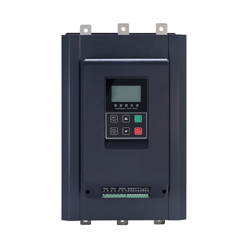 .
What soft starter installation includes (and what to read elsewhere)
Installation covers mechanical mount, line and load terminations, control wiring, grounding, and startup ramps—it does not replace SCR troubleshooting guides.
If the technician is already isolating failed thyristors, route them to the repair article. If the buyer is comparing reactor current limit to SCR soft start, use the current-limit comparison article instead of duplicating selection economics here.
LNC820 general-purpose VFD panel wiring belongs in the VFD installation guide—this page covers online soft starter buckets only, not inverter output terminals or PWM motor cable rules.
Pre-install survey: nameplate, duty, and starter class
Photograph motor nameplate FLA, voltage, and service factor, then match the soft starter catalog row before you drill mounting holes.
Online soft starters sit in series with the motor feed; bypass styles add run contactors that change heat and wiring paths—your soft starter installation checklist must record which topology is on the nameplate sticker inside the door.
Document expected starts per hour and load inertia; ramp times that work on a fan may trip overload on a high-inertia crusher if parameters are copied blindly.
Clearance and environment checks belong in the survey: leave service space for ventilation, keep conductive debris out of the bucket, and confirm the enclosure rating matches the MCC room—not every soft start panel install fails on SCRs; some fail because heat and dust were ignored before energize.
Online soft starter installation projects should note whether the utility expects visible disconnect handle position, whether the MCC bucket has spare control terminals, and who owns the interlock to upstream process equipment—those details rarely appear on marketing pages but decide whether the first start is smooth or immediately tripped on a missing aux contact.
Line-side wiring, disconnecting means, and overload placement
Line-side terminals on the starter receive utility feed conductors after the disconnect is open and voltage is measured—this is the first mechanical landing point in most online soft starter wiring diagrams, separate from control terminal strips.
Line-side conductors need the correct voltage class and torque on lugs; branch disconnect and overload coordination follow local practice and the starter manual—this article stays at checklist level without inventing amp tables.
US integrators usually frame motor-branch work under NEC Article 430 and the starter manual; export machinery panels often reference IEC 60204-1 for disconnecting means and protective bonding—local adoption still decides, and this page does not quote paywalled clause text.
Industrial wiring references describe listed conductors, disconnecting means, and overcurrent devices in defined order; the starter manual supplies terminal labels and tightening specs you must follow on site.
Torque sequences matter on multi-conductor lugs: undertightened soft starter installation joints show up as heat at run mode, while overtightened lugs damage plating and invite intermittent faults that look like SCR damage in troubleshooting calls. Record torque values used on line, load, and PE studs in the turnover package so the next contractor does not guess.
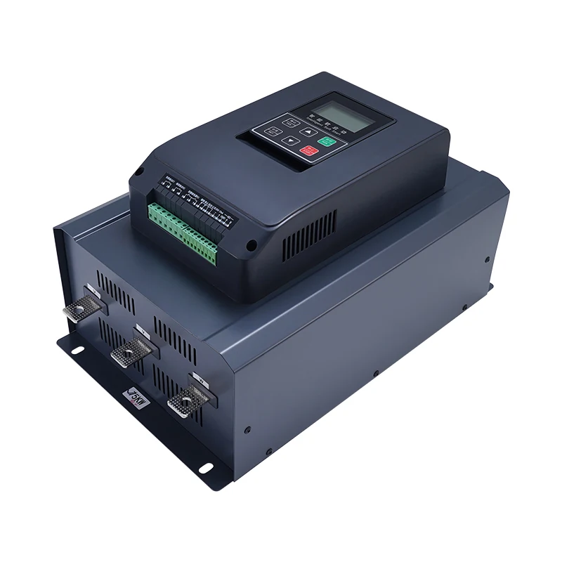 .
Motor-side terminals, bypass contactors, and run mode
Motor-side lugs carry load current during start and run; on bypass starters the contactor shunts SCRs after the ramp completes—miswired bypass mimics “starter never ramps” faults in the field.
Verify auxiliary contacts that prove bypass status tie into the control scheme your PLC expects; otherwise run-mode heat lands on the wrong stage.
Control power, start/stop, and interlock circuits
Control circuits typically include start, stop, reset, and sometimes external trip inputs—soft starter installation quality is often decided here when low-voltage commons float between panels.
Separate control power return paths per the diagram; do not share neutrals in ways that defeat fault monitoring features documented on the product page.
Two-wire versus three-wire start/stop conventions still vary by panel legacy; your soft starter installation drawing should show holding contact wiring explicitly so a remote stop from a safety PLC does not conflict with local maintainers. Label control terminals with the same names the manual uses—renamed wires are a common source of “starter runs in test but not in production” callbacks.
Grounding, bonding, and cabinet inspection before energize
Protective earth (PE) must land on the starter PE stud with correct torque; cabinet inspection catches loose shipping brackets and debris before first energize.
Important: No soft starter installation step on live terminals is acceptable—prove zero energy with lockout/tagout before you torque line, load, or control connections, then re-run the same discipline after any rework.
Grounding articles remind readers that fault paths and shield termination matter for EMC even on reduced-voltage starters—follow the manufacturer drawing for motor cable shields.
| Install checkpoint | Pass criteria | Common miss |
|---|---|---|
| PE torque | Manual spec on PE stud | Star washer only, no low-impedance path |
| Control wire class | Listed voltage rating | Mixing PLC low voltage with line-voltage aux |
| Bypass aux proof | Contact matches run state | Welded bypass not detected |
| Ramp initial | Low current limit on first start | Copied aggressive ramp from unlike load |
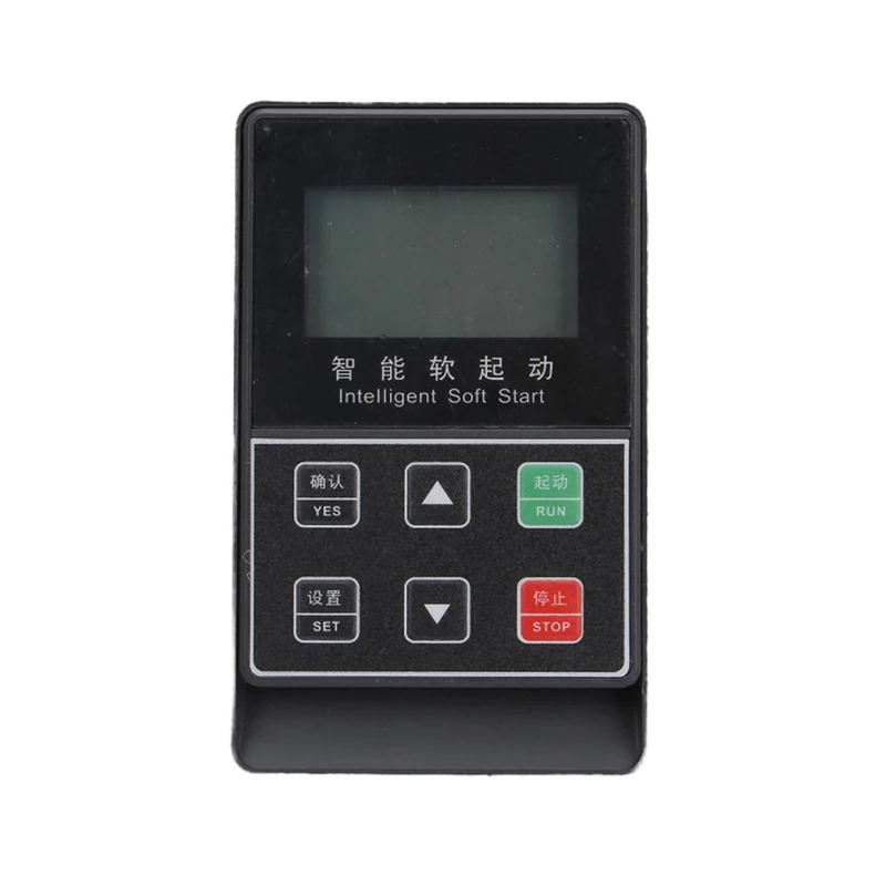 .
Commissioning ramps, current limits, and first start
Commissioning sets initial ramp time and current limit conservatively, then walks up after successful starts—mirroring field practice discussed on machinery electrical equipment standards pages for ordered startup.
Record final parameters on the turnover sheet; maintenance inherits the same ramp after a starter swap.
First start should be witnessed: listen for bypass pickup, note current draw versus nameplate FLA, and confirm overload does not trip on a healthy load. If the motor does not reach expected speed before bypass, stop and compare ramp and current limit settings to the manufacturer starting curve guidance rather than stacking repeated hot starts.
Document auxiliary contacts wired during soft start panel install—future troubleshooting assumes those proofs exist, and missing aux wiring is a common reason production refuses to accept a bucket even when the motor ramps cleanly in maintenance mode.
Matching ZR800 online soft starter series — product fit for installation projects
Catalog rows anchor install RFQs after wiring checks—not before them.
When the application is pump or fan duty and you want a catalog-backed online soft starter example from this site, public ZR800-18.5-90KW Online Soft Starter pages document comprehensive protection, monitoring of current/voltage/phase sequence, configurable fault enable/disable, and a features list that cites analog output and monitoring bullets on the public page—cite published page bullets only, not unlisted install services.
Larger kW bands in the ZR800 family on the site follow the same online topology with different enclosure sizes—match the ordered row to motor FLA and starts-per-hour duty.
| Published ZR800 theme | Install relevance | Your site still verifies |
|---|---|---|
| Published protection list (feature list) | Sets expectation for fault LEDs during commissioning | Which faults are enabled day one |
| Monitoring of current/voltage/phase | Helps first-start troubleshooting | Sensor calibration, CT orientation |
| Configurable fault enable/disable | Commissioning without nuisance trips | Lockout after tuning |
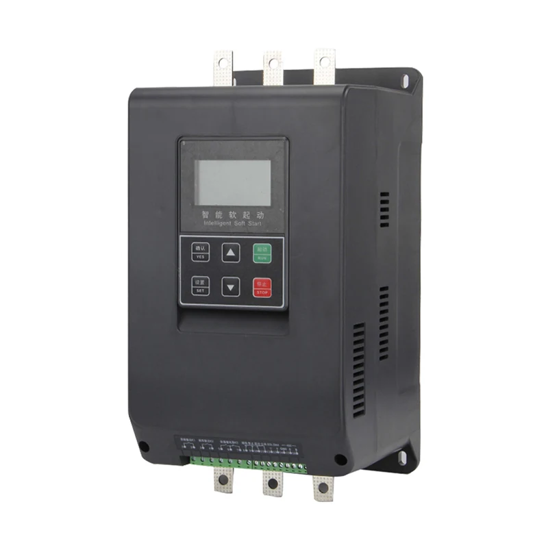 .
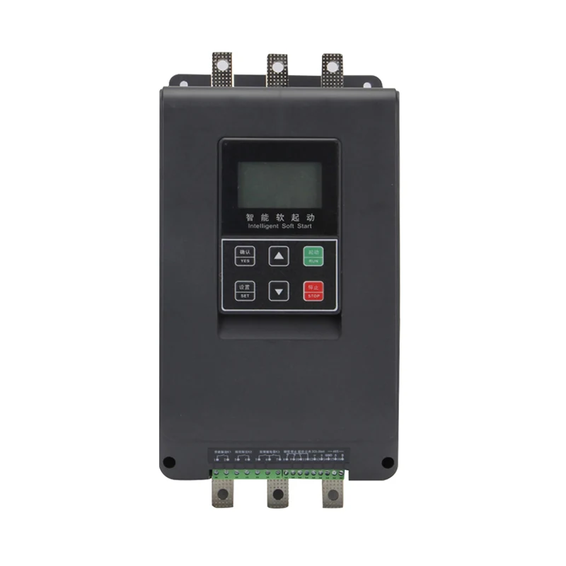 .
Share motor nameplate photos, expected starts per hour, and bypass versus online requirement when you confirm ZR800 kW row fit with the supplier.
Add photos of the MCC bucket label, disconnect nameplate, and control terminal strip before you close the install package—those three images shorten remote support calls when a ramp trips on first production start.
Label every control wire you move during online soft starter wiring with the same terminal designation shown on the drawing; unnamed spares in the bucket become tomorrow’s intermittent trip that no shift log explains.
Frequently Asked Questions
These answers stay at installation scope; fault isolation steps live in the soft starter repair guide.
Does soft starter installation require a VFD?
No. Soft starters limit voltage ramp; they do not provide continuous speed control—keep VFD wiring guides separate.
Where is the bypass wired?
Follow the manufacturer diagram for your ZR800 row; bypass contactor aux must match your control scheme.
Can I install without locking out?
No. Prove zero energy before terminal work—repair guides cover test sequences after isolation.
What breaker size do I need?
Branch protection follows local code and the manual—do not copy unrelated VFD breaker articles without nameplate data.
How is this different from soft starter repair?
Installation is first-time wiring and commissioning; repair is fault isolation on an existing unit.
Does installation include harmonic filters?
Only if specified on the order—line-side conditioning is a separate application decision.


