




VFD flying start is a function that lets a compatible drive detect and take control of a motor that is already rotating, instead of treating every start as a start from rest. It can help with coasting fans and other loads after a permitted interruption, but it does not decide whether restarting the machine is safe. Confirm motor compatibility, direction handling, restart permissions and the actual drive instructions before enabling it. Acceptance must cover the moving load and the machine sequence together. This guide addresses controlled recapture of rotation, rather than a universal parameter recipe.
Recognize a moving-motor restart problem
A fan can keep rotating after the inverter stops producing torque. Airflow through the duct may also turn it independently. A pump or another driven mechanism can move for process reasons even when the drive has no run command. Do not assume that a stopped output display proves the shaft is stationary.
A normal start from zero output frequency may be unsuitable when the motor is still turning. The drive and rotating machine begin in different states, and the resulting transient can interrupt the restart. Capture the actual event: what removed torque, how long the interruption lasted, the mechanical direction and the command that requested recovery. Avoid diagnosing every start-related overcurrent as a flying-start problem.
The basic VFD operating principle explains how the inverter controls motor output. Flying start concerns the initial condition before normal acceleration, so it should be investigated separately from an ordinary ramp-time adjustment or a fault during steady running.
Understand the principle without copying another drive’s parameters
A flying-start routine establishes a usable estimate of the rotating motor’s state and transitions into torque-producing control. The method, search behavior and limits depend on the drive, motor and control mode. Some implementations use different detection or search strategies; a parameter name alone does not establish how the installed unit works.
The University of Rijeka paper Flying Start Routine for Induction Motor in Scalar Control Mode describes speed identification followed by magnetization and acceleration for an induction-machine routine. It supports the principle of matching a rotating machine, not a generic settings table. Its experiment is not a performance guarantee for another drive.
Texas Instruments’ motor startup documentation also distinguishes initial position handling, open-loop startup and detection of an already spinning rotor. It documents a particular control implementation. Do not transfer its software states, sensing claims or thresholds to an industrial VFD without confirmation.
Keep recapture separate from automatic restart permission
Flying start answers how a compatible drive can resume control of a moving motor. Automatic restart logic answers whether and when a run command can be accepted after an event. The two functions may interact, but enabling one does not justify the other. Review fault reset, maintained run commands, communication recovery and power restoration as separate cases.
A machine that must remain stopped after a guard event must retain that behavior. A process designed for automatic recovery requires its own risk assessment, permissives and warnings. Do not turn on restart retries merely to demonstrate speed tracking, and do not use the feature to defeat a stop function or safety interlock.
HSE’s guidance on controls for starting equipment discusses deliberate starting actions and the distinction from normal automatic cycles. This is UK work-equipment guidance; the project must also establish the rules applicable to the destination and machine. The practical task is to write down which interruption categories permit recovery and which require a deliberate new start.
Verify product and motor compatibility
Obtain the exact drive identification, firmware, motor type, nameplate and current parameter backup. Confirm that speed tracking is supported for that motor and selected control mode. An induction-motor procedure should not be assumed valid for a permanent-magnet or synchronous-reluctance motor. Ask the supplier about direction search, allowed rotation range, detection limitations and any required feedback.
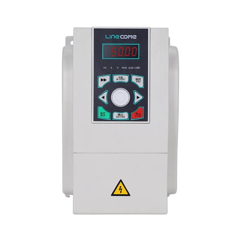
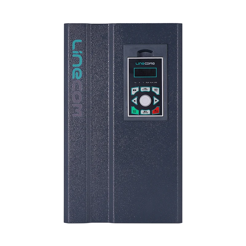
The LINECOME LNC860S vector VFD product page lists speed tracking among the series functions. That establishes a relevant product discussion, while the actual settings, supported modes and acceptance limits must be confirmed in the supplied documentation. The photographs below illustrate related series housings; they do not establish a particular firmware configuration.
Check the complete motor connection path. A changeover system, output contactor or disconnected motor branch can invalidate the conditions under which tracking was configured. Any switching between the drive and motor must follow an engineered sequence approved for the equipment. Do not operate an output isolator as an experimental restart control while the drive is producing output.
Write a restart decision table
Use this qualitative table to organize the review. It is an original acceptance-planning worksheet based on the distinction between moving-motor capture and machine permission, rather than a set of manufacturer limits.
| Initial condition | Decision before requesting a start | Evidence required |
|---|---|---|
| Motor confirmed at rest | Use the approved stationary start sequence | Correct motor data and repeatable ordinary start |
| Motor coasting in intended direction | Confirm compatible tracking and permitted recovery | Observed direction, drive state and capture behavior |
| Load drives motor in reverse | Obtain explicit reverse-rotation handling instructions | Process cause, allowed direction and supplier-approved sequence |
| Guard or emergency stop has operated | Preserve the machine’s required reset and start behavior | Verified permission logic and safety test record |
| Power returns with run command maintained | Establish whether a new start is authorized | Documented restoration policy and command-state trace |
| Tracking repeatedly fails | Stop retries and investigate the actual boundary | Fault record, motor data, connection path and operating condition |
Define who decides each branch. A drive technician may configure the control mode, while the machine designer owns restart permissions and the process engineer understands backflow or windmilling. Leaving these responsibilities implicit can produce a drive that captures speed correctly but restarts at an unacceptable time.
Establish the baseline from a stationary start
Before testing a moving motor, verify a normal start under the approved setup. Confirm motor data, direction and load behavior. Record the command source, speed reference, fault state and relevant current indication. If the stationary start is unreliable, resolve that problem before adding another changing initial condition.
Back up the configuration and record every intentional change. Use the manufacturer’s commissioning procedure for identification or tuning; some routines require a stationary or uncoupled motor and must not be run on a rotating process load. Establish whether the machine can safely satisfy those requirements before starting the routine.
Review existing overcurrent fault evidence and overvoltage fault history where relevant. Keep the event timing clear: an issue during initial capture differs from one while decelerating after capture. Correcting an unrelated fault by increasing limits would conceal the diagnostic boundary and could reduce equipment protection.
Test a coasting restart under controlled conditions
Write the test procedure with the responsible machine and process personnel. Specify how torque will be removed, how rotation will be observed, when a start may be requested and what observations require the test to stop. Identify people who could be affected by an unexpected movement, and establish the required guarding and exclusion arrangements.
Begin with a permitted condition that the manufacturer says is suitable for tracking. Record the initial direction and rotation condition, elapsed interruption, run request, drive status, reference and resulting acceleration. Use time-aligned logs when available. A test report that says only “flying start enabled” does not show whether the routine was invoked or the machine simply happened to stop first.
Progress to other representative conditions only after the initial result is acceptable. Do not deliberately create reverse rotation, supply faults or hazardous process disturbances just to fill a test matrix. If an important condition cannot be reproduced safely, document it as an untested boundary and agree on another validation method with the supplier.
Observe both electrical and process behavior. A successful drive status does not prove that a pump restart avoids an unacceptable pressure event or that a fan captures without mechanical disturbance. Define those acceptance criteria from the actual application. No universal frequency, delay or current setting can substitute for this assessment.
Investigate failed capture without endless retries
If the routine fails, preserve the first fault and return to a safe state. Check whether tracking was actually enabled for the relevant event, whether the correct motor dataset was active and whether the output path remained connected as intended. Compare the observed direction with the configured handling. Verify the firmware instructions rather than translating a parameter from another drive family.
Next review the command sequence. A PLC may remove enable while retaining run, reset a fault and immediately restore a command, or switch speed sources during recovery. These actions can alter the initial condition seen by the drive. Trace the real states before changing detection settings.
Repeated restarts add thermal and mechanical duty and may obscure the original event. Agree on a maximum test sequence and cooling requirements with the equipment supplier. If the drive cannot safely capture the expected rotation, the solution may involve process changes, a different permitted stopping sequence or revised equipment selection; it is not automatically a more aggressive search setting.
Prepare a useful specification and handover
For an RFQ, provide motor type and nameplate, drive identification, load inertia information where known, expected coast behavior, possible reverse rotation and the events that trigger recovery. Include the motor connection arrangement, required command sources and the machine’s restart policy. State which operating conditions need supplier demonstration.
For handover, retain the original and final parameter sets, approved test matrix, event traces and signed acceptance results. Identify untested conditions and any restrictions on automatic recovery. Train operators to distinguish normal tracking delay from a fault and to avoid repeated reset attempts when capture fails.
Recheck the sequence after changes to motor data, firmware, control mode, output switching or process equipment. A setting that worked before a fan or duct modification is not permanent proof for a changed installation. The useful outcome is a documented recovery function whose electrical behavior and permission logic remain aligned.
Further learning: induction motor rotation
The following educational animation explains rotating magnetic fields and slip in induction motors. It helps explain why rotor motion matters at restart; it does not demonstrate flying-start settings or certify a particular VFD’s capture performance.
Video by Sabin Civil Engineering. Watch How does an Induction Motor work ? on YouTube.
Frequently asked questions
Is VFD flying start the same as automatic restart?
No. Flying start concerns taking control of an already rotating compatible motor. Automatic restart determines whether a run request may occur after an event. Both must follow the machine’s approved operating and safety requirements.
Can flying start catch a motor rotating backward?
That depends on the drive, motor, control mode and configured direction handling. Obtain explicit manufacturer guidance and assess the process cause of reverse rotation before allowing a restart.
Can I use another drive brand’s flying-start settings?
Do not copy parameter numbers or values across products. Confirm the installed model, firmware, motor data and supported control mode, then validate the approved configuration under representative permitted conditions.


