




VFD motor nameplate settings should describe the motor actually connected to the drive: its rated voltage for the selected winding connection, full-load current, rated frequency, power and full-load speed. Enter those values in the fields identified by the exact drive manual, then save and independently read them back. Do not substitute the drive’s own current rating, the supply frequency or a desired running speed for motor data. A copied parameter file is only a starting point when the connected motor, firmware and application have been checked.
This guide focuses on the information handover between a motor nameplate and a commissioned drive. The broader VFD operating-principle guide explains power conversion. Parameter numbers, permitted ranges and identification procedures remain specific to the selected equipment.
Start with a traceable motor record
Photograph the complete nameplate and record the equipment tag, motor model and serial number. Capture the connection diagram as well as the large voltage and power figures. If a guard or installation position prevents a readable photograph, arrange safe access during isolation. Do not reconstruct missing values from a similar-looking motor or a catalogue photograph.
The US Department of Energy motor survey guide identifies voltage, wired-for voltage, full-load current, power, full-load speed and other nameplate information as useful survey records. For commissioning, put the original evidence beside the proposed entries so another reviewer can check every transfer.
Keep three records separate: what the motor nameplate says, how the motor terminals are actually connected, and what the drive currently stores. Agreement between only two does not establish that the complete installation is correct. Mark any illegible or conflicting item as unresolved before scheduling a first run.
Select the correct voltage and connection pair
A motor may show more than one voltage, with different corresponding currents and terminal arrangements. Select the combination that matches the engineered installation. A photograph of links in a terminal box supports the connection record, but the diagram and motor instructions establish their meaning. Qualified personnel should verify the connection under the applicable isolation procedure.
Do not assume that a higher input supply voltage automatically permits that voltage at every motor winding. Equally, do not read the lower voltage and higher current from different columns as a valid pair. Maintain one complete row of the manufacturer’s data through the commissioning worksheet.
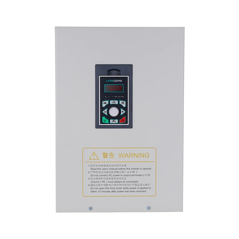
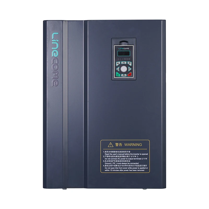
An enquiry for a LINECOME LNC860S vector VFD should include this motor record and the available supply details. The product page identifies a drive family; it does not establish the winding connection or approved settings for an unidentified motor.
Keep rated current distinct from drive capacity
Motor rated current describes the motor under its stated rated conditions. The drive has its own input and output ratings. Those values answer different questions and should occupy different worksheet fields. Using the larger drive rating as the motor current entry can corrupt the basis on which supported motor functions operate.
Before entering a current, check the unit and the voltage column. Read decimal points carefully on worn labels. Where the manual distinguishes rated motor current, current limit and thermal protection settings, record each separately. Do not multiply a nameplate current by a service factor unless the exact application instructions require that treatment.
A replacement drive can have more current capacity than the previous unit while driving the same motor. That does not justify increasing the motor’s nameplate entry. Any change to protection or permitted loading requires its own documented review, rather than being hidden inside a routine parameter transfer.
Separate rated frequency from a speed command
Rated motor frequency belongs to the motor’s defined operating point. A frequency reference tells the drive where the process currently wants to run. Minimum and maximum frequency settings define separate operating boundaries. These fields can contain different numbers without contradicting each other.
For example, changing a process reference during testing should not require rewriting the motor’s rated frequency. If an imported parameter set shows the site’s line frequency in a motor field, compare it with the actual nameplate rather than accepting it because the machine is installed in that country.
Ask the motor and machine suppliers to confirm the permitted speed range, including cooling and mechanical limits. Nameplate entry alone does not approve overspeed operation or prolonged low-speed loading. Use our low-speed motor overheating guide when the intended operating range raises a separate thermal question.
Read full-load speed as the motor’s rated speed
For an induction motor, the labelled full-load speed is different from the synchronous speed associated with frequency and pole count. Enter the value requested by the drive’s motor-data field rather than replacing it with a rounded synchronous value. The motor type must also agree with the actual machine.
The DOE motor-systems assessment training includes rated-load rpm, frequency, phases and duty among nameplate information. These items help distinguish a motor identity from a desired process speed, gearbox output speed or controller display unit.
If the driven machine has a gearbox, record both motor and load speeds with explicit labels. A conveyor shaft speed copied into a motor rpm field is a data error even when the conveyor itself runs smoothly. Resolve ambiguous nameplates with the motor supplier before relying on automatic identification.
Use a field-by-field review table
The table below is an original commissioning worksheet structure. It contains no universal parameter numbers or acceptance limits. Its purpose is to make the evidence behind each entry visible; the approved drive and motor documentation governs the actual values.
| Item | Evidence to collect | Cross-check before acceptance |
|---|---|---|
| Motor type | Model and motor documentation | Selected control mode supports that motor |
| Rated voltage | Nameplate row and connection diagram | Actual terminal connection matches the selected row |
| Rated current | Current from the same voltage row | Motor value is separate from drive output capacity |
| Rated power | Nameplate number and unit | kW and horsepower have not been interchanged |
| Rated frequency | Motor’s stated rated operating point | Separate from command frequency and speed limits |
| Rated speed | Full-load motor rpm | Not synchronous speed or gearbox output speed |
| Cooling and feedback | Motor and installed accessory records | Any required extra configuration is addressed |
Have the reviewer sign the completed table before the run authorisation. An empty cell is useful evidence of a remaining question; a guessed number conceals that question. Keep manufacturer correspondence attached where it resolves a missing entry.
Treat autotuning as a separate controlled task
Correct nameplate entries do not mean that every drive supports the same identification procedure. Some procedures may rotate the motor or impose conditions on the connected load. Follow the exact manual and the machine’s approved safe-work arrangement before enabling identification or accepting motion.
Record whether identification was required, which supported method was selected, whether the load was connected, and the result. If a procedure cannot be performed under the permitted conditions, obtain an approved alternative. Do not describe an unperformed identification routine as successful merely because basic motor data were saved.
For permanent-magnet applications, consult the separate PM motor autotune guide. Its additional motor and control considerations should not be transferred automatically to an induction motor, nor should induction-motor assumptions be applied to a permanent-magnet machine.
Verify the stored values after saving
A useful acceptance check reads values from the drive after the save operation and compares them with the approved worksheet. Checking only the numbers displayed before pressing save misses an important step. Where the manual permits, include an authorised restart or power-cycle check to establish that the required data persist.
Keep a dated export with the drive model, firmware and motor tag. Label the backup with the actual machine identity rather than only the technician’s laptop folder name. If a parameter tool translates units or changes the display format, preserve enough information to compare the engineering values consistently.
During an approved test run, record command frequency, indicated speed, motor current and the observed process response at agreed operating points. These observations are evidence for the commissioning record, not permission to change uncertain nameplate data until the symptoms disappear.
Specify what a replacement-drive handover must include
Request the motor nameplate photograph, verified connection record, approved motor-data worksheet, final parameter export and test report. Identify which settings describe the motor and which describe start commands, analogue signals, communications or process limits. A drive replacement involves all of these groups, although this article addresses only the first.
Ask the supplier to list unresolved assumptions before shipment. If the connected motor changes after factory testing, reopen the motor-data review instead of retaining the earlier approval by default. The handover should identify who can authorise that change and where the revised backup will be stored.
A good record lets the next technician distinguish an intentional application setting from a transcription error. That is more valuable than a long list of unexplained parameter numbers copied from another machine.
Watch a motor-data configuration example
The RealPars lesson below demonstrates motor-data entry in a named software environment. Use it to understand the separation between motor information and drive configuration. Its equipment, numerical examples and screen labels are not LINECOME settings and should not be copied to a different installation.
Video by RealPars. Watch How to Control a VFD with a PLC – Part 4 (Configuring Motor Data in the Siemens Starter Software) on YouTube.
Frequently asked questions
Should the motor current entry match the drive’s current rating?
Use the motor rated current requested by the exact drive manual, from the nameplate row matching the installed connection. Drive capacity and motor current are separate records; a larger drive does not change the motor’s nameplate.
Can rated motor speed be replaced with synchronous speed?
Do not substitute a calculated or rounded speed where the field requests nameplate full-load rpm. Confirm the motor type and the meaning of the parameter, then enter the supported motor value.
Does entering nameplate data complete commissioning?
No. Stored-data readback, any required identification procedure, protection review, command checks and an approved machine test remain separate steps. Retain their results with the final backup before accepting the installation.


