




VFD installation is the field work of mounting the drive, landing line and motor conductors on the correct terminals, bonding protective earth, and following the manufacturer startup sequence—not repeating inverter theory from a mechanism article.
Successful vfd installation means your measured supply matches the published voltage class, your panel meets environment limits, and your wiring diagram—not a generic web sketch—defines where PE and motor shields terminate before you jog the motor.
Use the Variable Frequency Drive hub when you need drive family options after you confirm install constraints.
 .
What field VFD installation includes (and what to read elsewhere)
Field installation covers mechanical mount, electrical termination, grounding discipline, and ordered commissioning; it does not replace a deep dive on rectifiers, DC buses, or PWM switching.
If the buyer only needs to know how power flows inside the drive, point them to /blog/how-vfd-works/ for mechanism context. If the job is converting or adapting supply phase at the service, /blog/single-phase-to-3-phase-vfd/ addresses that decision path—here the focus stays on terminals, clearance, and startup order once a compatible drive is selected.
Community editors on the VFD talk page repeatedly separate “how it works” articles from line-side protection, harmonics, and wiring practice—your checklist should mirror that boundary on the shop floor.
Mounting clearance, heat, and environment before you strip wires
Clearance and environment checks belong before you strip insulation, because heat, dust, and vibration derate a drive even when the wiring looks neat.
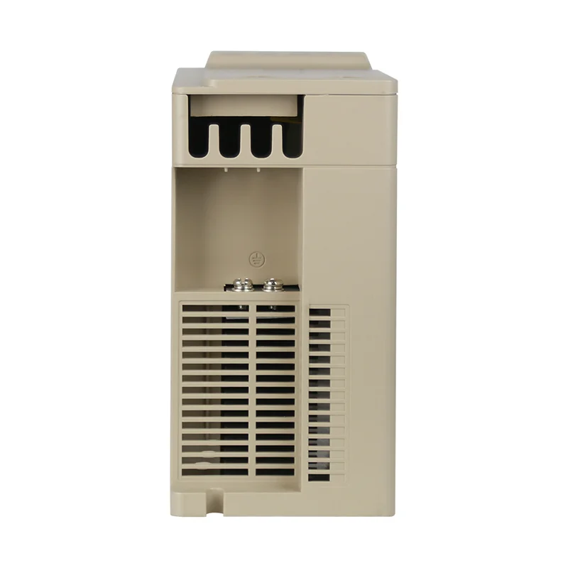
The public LNC610 environment table targets indoor use without direct sunlight, free from corrosive or flammable atmospheres, oil mist, dripping water, or salt spray. Published limits include altitude less than 1000 m, vibration less than 5.9 m/s² (0.6g), and humidity less than 95% RH without condensation.
Leave airflow space per the overall installation dimensions on the product page—do not stack drives against a hot transformer or cover vents with a cable tray. When multiple drives share a cabinet, treat each unit’s clearance as additive heat load instead of treating physical fit as thermal fit.
 .
NEC and IEC machinery framing for VFD installs (without wire-size tables)
Code and machinery standards set the frame; the drive manual and listing data supply the numbers—no universal wire-size table appears here.
In United States projects, NFPA 70 National Electrical Code Article 430 is the usual starting point for motor circuits and motor controllers, including variable frequency drives, subject to local adoption. Article 430 expects appropriate disconnecting means and branch protection coordinated with manufacturer data rather than guesswork.
Export machinery panels often reference IEC 60204-1 for electrical equipment of machines—supply disconnecting devices, protective bonding, and separation between power and control circuits. That standard describes the panel builder’s obligations; terminal labels still come from the drive wiring diagram.
| Frame | What it gives the installer | What the manual still owns |
|---|---|---|
| NEC Article 430 (US) | Motor-branch and controller context | Terminal torque and diagram detail |
| IEC 60204-1 (machinery) | Disconnect and bonding expectations on machine panels | Model-specific reactor or filter kits |
| Drive installation manual | Terminal map, commissioning steps | Cable gauge and protection rows |
Qualified designers still stamp ampacity, breaker rows, and short-circuit ratings—the install checklist here stops at discipline and handoff, not stamped design calcs.
Line-side terminals, disconnect, and branch-protection handoff
Line-side work starts at the open disconnect: measure voltage and phase class, then land conductors only on the input terminals the diagram labels for your supply.
The public LNC610 parameter table lists single-phase power supply 220 V ±10% with an actual permissible range of AC 198 V–242 V at 50/60 Hz, and three-phase 380 V ±15% with permissible range AC 323 V–437 V at 50/60 Hz. Those rows are supply-class gates—if the meter disagrees, stop before you torque lugs on R, S, and T (or the manufacturer’s equivalent labels).
Place branch overcurrent protection and the visible disconnect where your wiring rules and the manual expect them on the feeder ahead of the converter input. Branch breaker or fuse sizing is its own specification task; collect manual input current and maximum listed upstream device data in the RFQ rather than copying motor full-load amps from the shaft end.
Control power for digital inputs may share the same enclosure but should follow the manual’s separation from power lugs. Keep low-voltage control away from unshielded motor leads even when the panel looks spacious.
 .
VFD grounding, bonding, and motor cable shields
Grounding provides the fault path; shield termination controls EMC—both must follow the published vfd grounding diagram, not a habit from non-VFD motor starters.
Run an adequate protective earth (PE) conductor from the supply ground bus to the drive PE terminal shown on the wiring diagram. Bond enclosure doors and auxiliary metal parts per the machine standard your customer adopts.
Motor cable shields should terminate where the manufacturer specifies—community threads on drive grounding repeat the same correction: floating shields or tying shields at both ends without diagram approval invites noise on analog and communication circuits.
From the field: Installers who terminate motor shields at the drive end per the manual report fewer nuisance trips on analog speed references than teams who cut shields short “to avoid ground loops”—source note: Electrical Engineering Stack Exchange — How should I ground a VFD?.
Keep signal wires separated from motor power where the diagram shows crossing constraints; route shields with continuous low-inductance paths back to the PE point the manual names.
Motor-side terminals, routing, and published wiring diagram use
Motor-side work connects the inverter output to the motor terminals using the published vfd wiring diagram as the authority for lug labels, jumpers, and optional reactor locations.
Land conductors on U, V, and W (or the labeled output set) with torque values from the manual. Support the cable so terminal screws do not carry mechanical stress, and maintain bend radius suitable for shielded variable-frequency motor cable.
Long motor leads can amplify reflected-wave concerns on some installations; when lead length exceeds the manual’s comfort zone, ask the manufacturer about output reactors or approved cable types before you blame “bad tuning.”
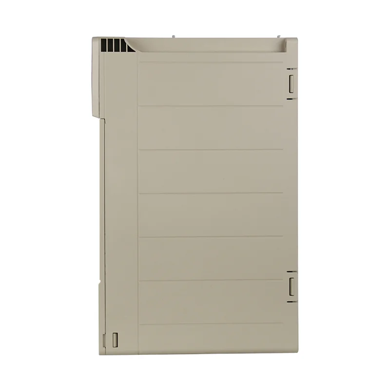
The LNC610 product page publishes a basic wiring diagram plus overall installation dimensions—use those assets in the RFQ so panel builders and field wiremen share one reference sheet.
 .
Commissioning order: verify, jog, then load
Commissioning is the ordered transition from “wired” to “production run,” and skipping steps is how new drives fault on the first start.
With supply locked out, recheck torque on power lugs, PE bonds, and control terminals. Restore power, confirm keypad or bus communication reads expected DC bus voltage without fault codes, and enter motor nameplate data into parameters before any run command.
Run a direction check at low frequency, then jog while someone watches mechanical coupling and brake hardware—remember many general-purpose frames ship without optional braking modules unless ordered. Only after jog and limit checks should you ramp to operating speed under load.
Document parameter backups and final direction for maintenance; future swaps depend on that record more than on memory.
LNC610 and LNC820 general-purpose VFD — product fit for field installation
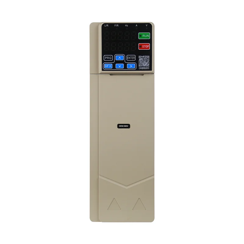
When your install pack needs a site-published general-purpose drive example, LNC610 and LNC820 families on vfdelec.com provide diagrams, environment data, and gallery assets alongside the exact model manual you must still download.
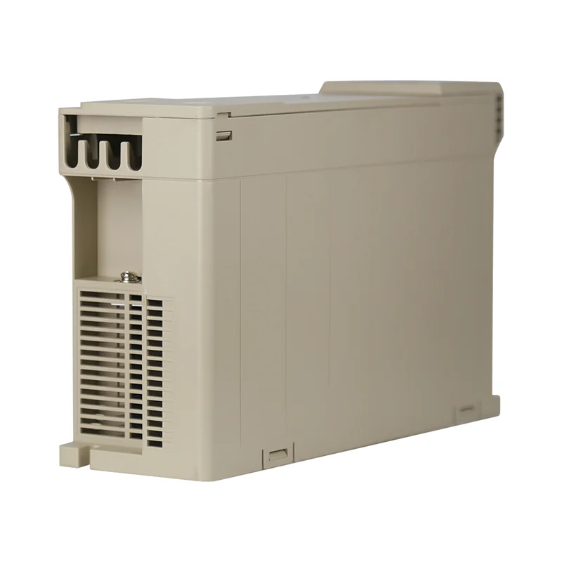
The public LNC610 2.2kW-220V-3.7-5.5kW-380V General-Purpose VFD product page publishes the parameter table with 198 V–242 V and 323 V–437 V classes, environment limits, basic wiring diagram, and installation dimensions discussed above. Overview copy notes the 610 series is not equipped with a braking unit by default—order braking hardware when the machine needs controlled deceleration.
When the machine environment or duty cycle demands higher protection positioning, review the LNC820 0.75-2.2KW General-Purpose VFD product page as an alternative general-purpose line on the same site; still download the diagram for the exact kW frame before you drill mount holes.
| Published LNC610 install asset | Why it helps the field team | Your project still must verify |
|---|---|---|
| Basic wiring diagram | Shared terminal labels in RFQ | Exact model variant and options |
| Overall installation dimensions | Panel cutouts and clearance | Heat load from neighboring gear |
| Environment table (1000 m, 5.9 m/s², 95% RH) | Go/no-go for site conditions | Local codes and listing sheet |
| Braking-unit note | BOM completeness | Manual braking resistor sizing |
Send supply photos, motor nameplate, desired cable routing, and the target product URL with the inquiry so the supplier confirms the frame—not just the marketing series name.
 .
Frequently Asked Questions
These answers stay at installation discipline; stamped calculations and final ampacity belong with the qualified designer and the drive manual for the model you order.
Does a VFD need a ground wire?
Yes. Protective earth connects the drive enclosure and fault path to the supply grounding system per the wiring diagram; skipping PE creates shock and EMC risk even if the motor runs briefly.
What is the correct order to power up a VFD?
Lock out, verify wiring and parameters, energize control and main power as the manual specifies, clear faults, jog at low speed, check direction, then ramp under load—never full-speed first start on a new install.
How far can a VFD be from the motor?
Distance limits are model-, cable-, and voltage-dependent; use the manual’s lead-length guidance and ask about output reactors when runs are long—do not assume unlimited distance because the mechanism article did not mention length.
Can I install a VFD in a cabinet with other drives?
You can when combined heat load, clearance, and ventilation satisfy each unit’s environment table; otherwise derate, fan, or relocate—fitting physically is not the same as fitting thermally.
Do I need an input reactor for every VFD install?
Not always. Reactors and filters address harmonics and line disturbances when the manual or utility demands them; treat them as a specification add-on, not a default BOM line on every small drive.
Should motor cable shields connect at both ends?
Only when the manufacturer diagram shows that termination pattern; otherwise follow the single-point scheme the manual gives—forum guesses are not commissioning data.
Is LNC610 braking hardware included by default?
Public LNC610 overview states the 610 series is not equipped with a braking unit by default; add braking function when you order if the machine needs it.
Where does branch breaker sizing fit in VFD installation?
After you know supply class and manual input data—size the upstream device during branch protection specification, not as a substitute for terminal torque or shield termination on install day.
References
- Variable-frequency drive — practical installation context.
- Ground (electricity) — protective earth and bonding concepts.
- Electrical wiring — disconnect and conductor discipline.
- NFPA 70 — motor branch and controller rules (US).
- IEC 60204-1 — Safety of machinery — electrical equipment.
- Talk:Variable-frequency drive — installation topics vs drive theory.


