




AC drive installation is the project work of placing an adjustable-frequency AC drive (VFD) in its enclosure, preparing line and load terminations per the manufacturer diagram, bonding protective earth, and handing off commissioning—not repeating inverter theory from a definitions article.
Successful ac drive installation planning means measured supply matches the published voltage class, panel clearance and heat load are verified before energization, and qualified electricians execute live wiring using the model-specific manual—buyers own the checklist up to that handoff.
Pair this page with the site’s VFD installation guide for terminal-level detail; here the language stays at AC drive buyer and panel-builder planning, distinct from soft starter installation or installing a soft starter reduced-voltage starter paths.
Use the Variable Frequency Drive hub when you need drive family options after install constraints are documented.
 .
AC drive installation scope for buyers and panel builders
AC drive installation covers mechanical mount, environmental fit, documented line/load interface points, grounding discipline, and an ordered commissioning plan—without substituting for stamped electrical design.
Buyers should confirm the drive model row, enclosure rating, and whether accessories (filters, reactors, braking units) belong in the BOM before installers torque lugs. Mechanism-only readers belong on what are VFD until they return with panel drawings.
Panel clearance and heat planning before the drive ships
Clearance and environment checks matter before conductors are landed, because stacked heat sources derate AC drives even when cables fit physically during ac drive panel planning.
Public LNC610 environment data on vfdelec.com targets indoor use without direct sunlight, corrosive or flammable atmospheres, oil mist, dripping water, or salt spray, with altitude below 1000 m, vibration below 5.9 m/s² (0.6g), and humidity below 95% RH without condensation—use those rows as planning gates alongside manufacturer clearance drawings.
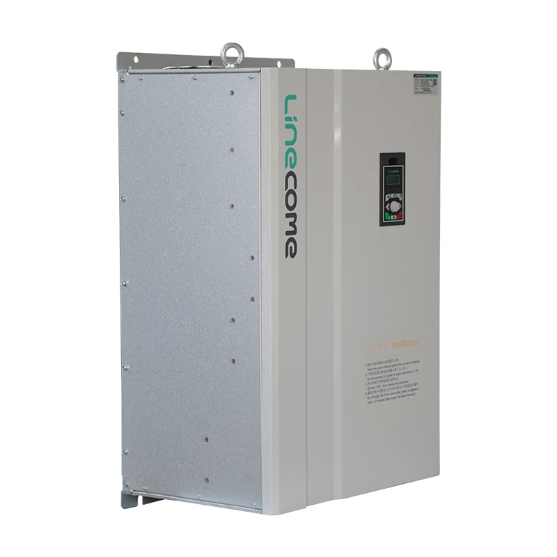
Leave airflow per the installation dimension figure on the product page; do not cover vents with cable trays or mount drives against hot transformers without a thermal review.
 .
Nameplate and supply-class checks before install planning
AC drive installation starts with nameplate truth: motor kW, voltage, phase, frequency, and service factor, plus the measured supply class at the planned disconnect—not assumptions from marketing titles.
The public LNC610 parameter table lists single-phase 220 V ±10% (permissible 198 V–242 V) and three-phase 380 V ±15% (permissible 323 V–437 V) at 50/60 Hz—if field measurements fall outside those published bands, stop and re-select the drive row before mounting hardware.
Document whether the upstream supply is single-phase or three-phase and capture photos for the RFQ packet installers will inherit.
Line-side handoff: disconnect, protection, and documentation
Line-side planning identifies line-side terminals, disconnecting means, and branch overcurrent placement relative to the drive input labels on the wiring diagram—qualified designers size protection; this buyer page does not publish amp tables.
Collect manufacturer input current data and maximum listed upstream device guidance from the manual for the exact catalog row. Control power wiring should follow separation shown on the diagram—low-voltage circuits routed away from unshielded motor leads even when the enclosure looks spacious.
 .
Load-side planning: motor leads, routing, and diagram ownership
Load-side work lands inverter output conductors on motor terminals U/V/W (or labeled equivalents) with torque values from the manual, proper cable support, and bend radius suited to shielded variable-frequency motor cable—markup the published vfd wiring diagram in the RFQ so ac drive panel planning reviewers share one document set.
Long motor leads may require output reactors or approved cable types on some installations—note lead length in the install packet so field teams ask the manufacturer before tuning is blamed for wiring stress.
Use the published basic wiring diagram on the product page as the shared reference between panel shop and maintenance— not a generic web sketch.
 .
Grounding and shield handoff to qualified installers
Protective earth (PE) and motor cable shield discipline must follow the manufacturer grounding diagram: equipotential bonding of enclosure parts and correct shield termination for EMC—not habits copied from non-VFD starters.
Community maintenance threads on drive installs repeat the same correction: floating motor shields or tying shields at both ends without diagram approval invites noise on analog speed references.
From the field: Teams that terminate shields at the point the manual names report fewer nuisance trips than crews that cut shields short “to avoid ground loops”—treat the diagram as commissioning data.
Qualified electricians perform live continuity and insulation checks; buyers supply the diagram PDF and panel layout photos in the handoff bundle.
Commissioning readiness without live-wire procedures
Commissioning order documentation is the ordered transition from “mounted and wired” to production run: parameter entry from motor nameplate, direction jog at low frequency, mechanical coupling checks, then loaded ramp—motor-side terminals must match the diagram before any run command is enabled.
Lock-out/tag-out, torque verification, and step-by-step energization belong in the manufacturer manual executed by qualified staff—this page stops at the readiness checklist maintenance should receive (parameter backup plan, direction record, fault log).
Cross-read VFD installation for terminal-level sequencing vocabulary without duplicating its section structure here.
Export machinery buyers should attach IEC-oriented panel standards only as pointers in the RFQ—qualified designers map local adoption—while still requiring the drive manufacturer diagram as the terminal authority. OEM project managers often bundle AC drive install planning with soft-starter quotes on the same machine; when the final design is adjustable-speed, discard soft-starter termination assumptions and reopen clearance checks because heat profiles differ.
| Handoff item | Buyer / panel shop supplies | Field electrician executes |
|---|---|---|
| Wiring diagram PDF | From exact product URL | Termination and torque |
| Nameplate photos | Motor and supply | Parameter entry |
| Clearance drawing | Panel layout | Mount and airflow verify |
| Shield plan | From manual | Termination pattern |
LNC610 and LNC820 product recommend for panel-ready AC drive projects
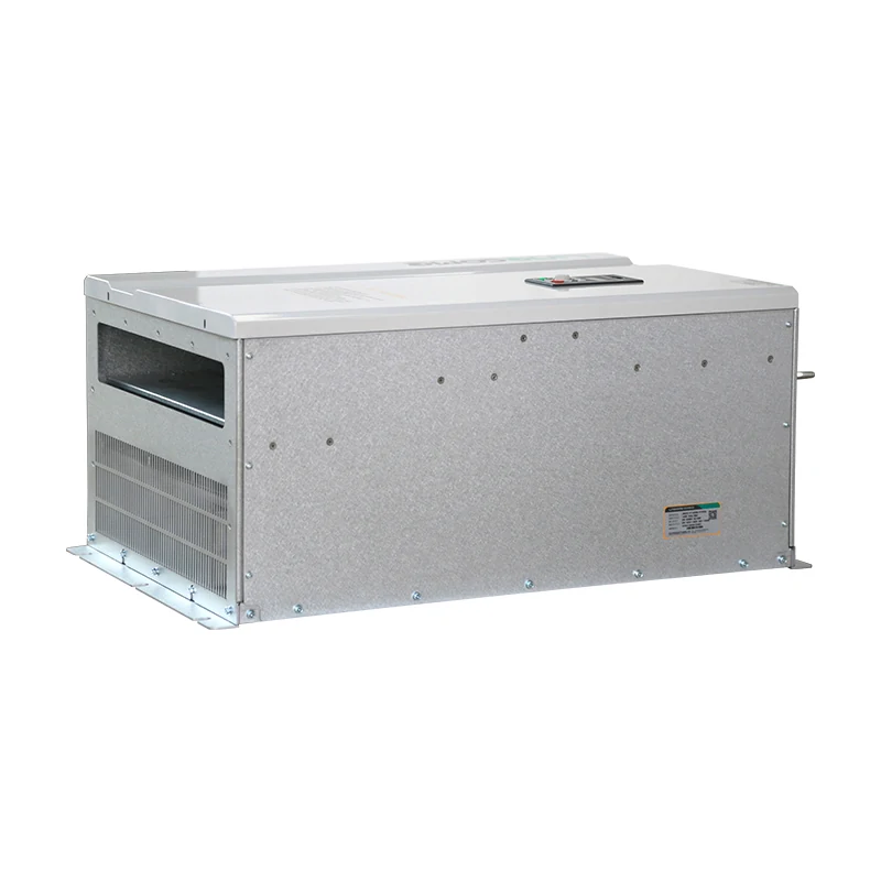
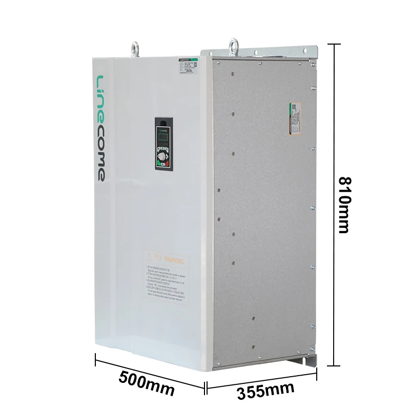
When nameplate and supply class match published rows, LNC610 general-purpose AC drives provide parameter tables, environment limits, wiring diagrams, and dimension drawings on vfdelec.com for panel-ready planning; LNC820 offers alternate kW bands on the same site when duty or enclosure positioning fits the public catalog split.
Public LNC610 copy notes the 610 series is not equipped with a braking unit by default—order braking hardware when the machine needs controlled deceleration. Download the diagram for the exact kW variant before cutouts are drilled.
| Install planning asset on public LNC610 page | Why panel builders use it | Still verify in field |
|---|---|---|
| Basic wiring diagram | Shared terminal labels | Exact option codes |
| Installation dimensions | Cutouts and clearance | Combined heat load |
| Environment table | Go/no-go for site air quality | Local codes via designer |
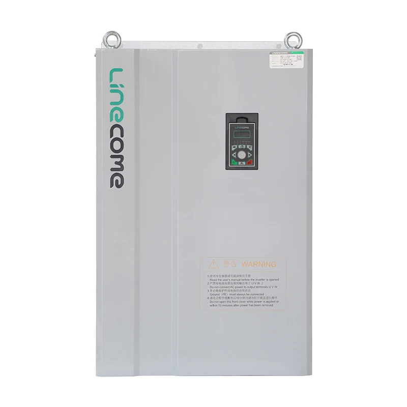 .
Link the specific LNC610 product page or LNC820 product page in RFQs so suppliers confirm the frame—not merely the words ac drive installation from a search bar.
Frequently Asked Questions
Short answers focus on ac drive installation planning; stamped ampacity and live testing stay with qualified designers and electricians.
Is AC drive installation the same as VFD installation?
The hardware class is the same adjustable-frequency drive; AC drive wording often appears in buyer RFQs while VFD wording appears in electrical drawings—use both labels but one manufacturer manual.
What clearance do AC drives need in a panel?
Follow the installation dimension figure and environment table on the exact product page plus manufacturer clearance notes—physical fit does not imply thermal fit when multiple heat sources share a cabinet.
Who should perform live wiring on an AC drive?
Qualified electricians or authorized service staff per local rules—buyers and panel shops deliver diagrams, nameplate data, and layout; they do not replace licensed execution on energized circuits.
What nameplate data matters before install planning?
Motor kW, voltage, phase, frequency, and service factor, plus measured supply class at the disconnect, drive input row selection and parameter defaults.
How does grounding differ from generic motor starters?
Drives require diagram-specific PE and motor shield termination for EMC; copying starter habits without the VFD grounding figure risks nuisance faults and noise.
When should I read the VFD installation terminal guide?
After panel layout and nameplate checks pass—open VFD installation when you need terminal label and commissioning-order detail beyond this AC-drive buyer checklist.
Does LNC610 include braking hardware by default?
Public LNC610 overview states the 610 series is not equipped with a braking unit by default—specify braking options when deceleration energy must be handled.
What environment limits apply to LNC820 panels?
Use the environment and clearance data on the specific LNC820 product URL you quote; harsh air quality or altitude above published limits requires engineering review even if the kW row matches the motor.
Facility managers scheduling production downtime should align mechanical mount, electrical handoff, and commissioning windows in one work order so AC drive swaps do not leave panels energized while clearance or shield steps remain incomplete.
References
- Variable-frequency drive — installation and application context.
- Electrical enclosure — cabinet layout and clearance concepts.
- Ground (electricity) — protective earth and bonding.
- Electric motor — nameplate data used in commissioning.
- Talk:Variable-frequency drive — field wiring versus drive theory.
Related practical guides
During commissioning, use the dedicated guides to VFD overvoltage fault troubleshooting and low-speed motor overheating checks to record operating conditions before changing drive settings.


