




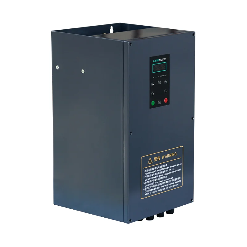
An industrial ac to ac frequency converter circuit on a motor-drive datasheet is the power chain that accepts fixed-frequency AC from the plant, processes it through a DC stage, and delivers new AC at the motor whose frequency and voltage are commanded electronically. If you are reviewing quotes—not building a bench circuit—start with the rectifier, DC link, and inverter blocks, then confirm control and protection sections separately. Treat the drawing as a vfd block diagram checklist, not a parts list for hand soldering.
Browse the Variable Frequency Drive hub when you need series comparisons after the block layout makes sense on paper.
 .
How this circuit page differs from Hz import and mechanism blogs
This URL is about block topology on VFD-class hardware, not about matching a 50 Hz nameplate to a 60 Hz utility, and not a repeat of control-mode physics.
Sibling pages already cover those jobs: how a VFD works walks speed physics and V/Hz versus vector commissioning; 50 to 60 Hz frequency converter and frequency converter from 60 Hz to 50 Hz focus on grid/nameplate mismatch; 400 Hz to 60 Hz frequency converter covers upstream 400 Hz bus planning; low-frequency vs high-frequency inverter efficiency discusses switching efficiency—not the three power blocks themselves.
Tip: When a vendor one-line says “AC-AC frequency converter,” ask for a block diagram first—source theme U-02 on Talk:Variable-frequency drive; programming base frequency belongs in commissioning documents referenced from the Hz articles above, not in place of power-stage labels.
Rectifier block: what the line-side converter does
The rectifier is the line-side AC-to-DC stage that converts incoming utility or transformer AC into direct current for the internal bus.
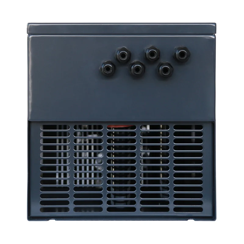
On general-purpose drives this is commonly a diode bridge on three-phase industrial units, while smaller single-phase input models still follow the same functional split: incoming AC becomes DC before any frequency change reaches the motor terminals. Protection devices, disconnects, and input reactors—when required—sit ahead of or around this block per the manufacturer drawing, not inside the inverter stage.
 .
DC link block: why the bus sits between stages
The DC link—usually a capacitor bank on voltage-source drives—smooths ripple and stores energy for the microseconds when the inverter switches.
Without a stiff bus, output pulses would collapse during fast transitions. Field questions about “why capacitors between rectifier and inverter” are really questions about this block’s role as an energy buffer, not about selecting discrete capacitor values for a DIY build. Pre-charge resistors, brake choppers, and DC bus monitoring appear on some catalogs as optional hardware tied to this section.
Inverter block: how AC frequency is commanded at the motor
The inverter is the motor-side DC-to-AC stage that switches the DC bus into pulses whose effective frequency and voltage track your speed reference.
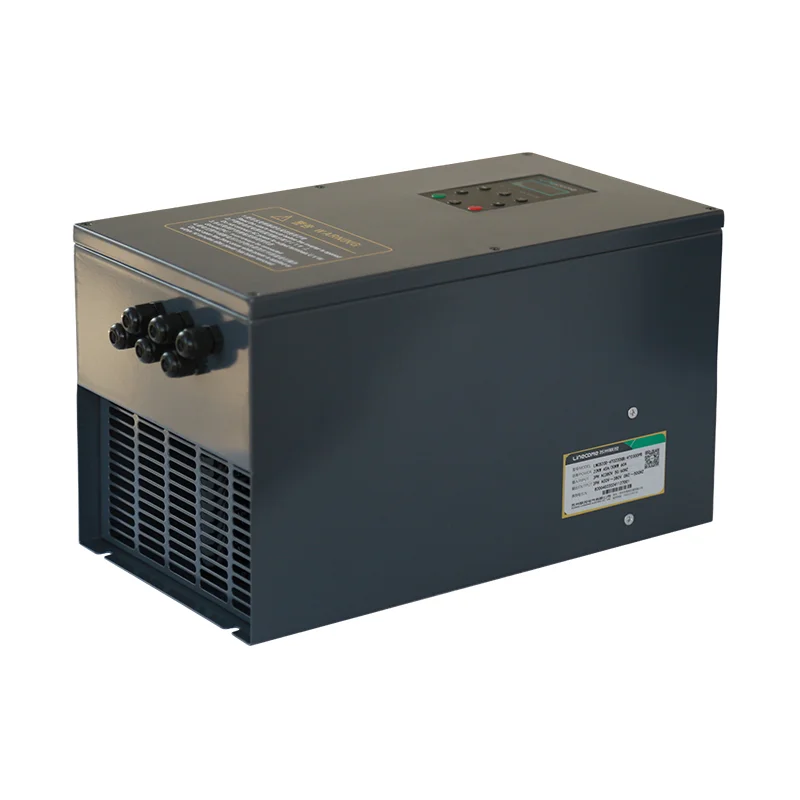
Pulse-width modulation (PWM) is the usual method on catalog VFDs: fast switching approximates a sine at the commanded frequency. This block is what buyers colloquially call the “frequency converter,” even though the entire cabinet performs AC→DC→AC conversion. Motor cable routing, shield termination, and output reactors—when specified—attach to this stage per the manual.
 .
| Power block | Input / output | Buyer question to ask on the diagram |
|---|---|---|
| Rectifier | AC in → DC out | Does input match my supply class and listed protection? |
| DC link | DC storage | Are pre-charge, brake, or bus-fault devices shown if my duty needs them? |
| Inverter | DC in → variable AC out | Is motor-side filtering or long-cable option documented? |
VFD vs frequency converter vs AC-AC labels on quotes
Procurement language overlaps: variable frequency drive, adjustable-speed drive, and frequency converter often describe the same three-block product when the load is an AC motor. When a drawing is labeled ac to ac converter circuit or a vfd block diagram, the same rectifier–DC link–inverter story usually applies.
“AC to AC” emphasizes that both sides of the power path remain alternating current at the terminals, even though the middle stage is DC. That wording does not by itself promise import/export grid conversion, aircraft 400 Hz feeds, or a rotary motor-generator set—those are different system stories with their own siblings on this site. Control electronics—keypad, PLC interface, PID—should appear as a parallel section on the diagram, not confused with the power blocks.
When cycloconverters differ from DC-link VFD circuits
Cycloconverters can change AC frequency directly without a large intermediate DC store on classic high-power layouts, whereas mainstream general-purpose VFDs use the rectifier–link–inverter (VSI) path described here.
If your specification names cycloconverter or matrix-style hardware, you are usually outside the LNC610/LNC820 general-purpose family context. For standard machine-builder motor branches, expect the three-block VSI drawing. Niche high-power projects need their own feasibility review—do not assume hobby-schematic parts lists apply.
Important: Community editors on Talk:Variable-frequency drive repeatedly separate topology education from utility frequency mismatch questions—source theme U-02; read the Hz sibling articles when the motor nameplate frequency differs from the plant feed, after you confirm the vendor diagram shows rectifier, link, and inverter.
Buyer checklist for block diagrams on datasheets
Use the checklist before you accept a one-line “AC-AC converter” SKU.
Confirm the drawing shows all three power blocks with clear line-side and motor-side terminals. Verify control power, digital I/O, and fieldbus ports are labeled separately from power semiconductors.
Ask whether optional input filters, output reactors, or brake units are part of the quoted model or loose options. Capture motor nameplate data, expected continuous speed range, and ambient limits on the RFQ—topology acceptance does not replace thermal or mechanical overspeed checks.
Panel builders often file annotated vfd block diagram PDFs beside the one-line so maintenance inherits the same block names the factory used during FAT.
 .
LNC610 and LNC820 product fit after topology acceptance
Once the rectifier → DC link → inverter layout matches your motor-branch architecture, catalog rows on vfdelec.com show what the inverter block is allowed to command on published tables—not a substitute for your motor duty study.
The public LNC610 general-purpose VFD series page lists output frequency 0–500 Hz, control modes V/F control and SVC vector control, and Modbus RS485 on the published parameter overview for the series. The public LNC820 general-purpose VFD series page lists 0–500 Hz output, V/F and SVC, and RS485 on its overview copy for the general-purpose line.
Match the ordered model to input voltage class, output current, and enclosure; then program base frequency and motor data during commissioning. Those steps connect to sibling Hz articles when the issue is nameplate frequency versus utility, not when the issue is recognizing inverter blocks on the datasheet.
| Public catalog item (series level) | Relevance after topology review | Your project still verifies |
|---|---|---|
| 0–500 Hz output range | Shows electronic frequency command span | Continuous torque, cooling, mechanical limits at lowest speed |
| V/F and SVC modes | Control layer above power blocks | Motor data entry, load type, tuning time |
| RS485 on overview | Integration path | Register map, baud, fault handling |
 .
Frequently asked questions
The questions below mirror how procurement and maintenance teams read vendor block diagrams—each answer stays at the topology layer defined on this page.
What is an AC to AC frequency converter circuit in industrial drives?
It is the rectifier, DC link, and inverter chain that converts fixed incoming AC to DC and back to frequency-controlled AC at the motor terminals on VFD-class hardware.
What does the rectifier block do in a VFD?
It performs line-side AC-to-DC conversion so the internal bus can feed the inverter stage.
Why is there a DC link between rectifier and inverter?
The DC link stores and smooths energy so the inverter can switch without collapsing the bus voltage during output transitions.
How is this different from a 50 Hz to 60 Hz import converter article?
Hz sibling articles cover nameplate versus utility frequency programming and project checklists; this page names the power blocks shared by those drives.
Is a cycloconverter the same block diagram as a VFD?
No. Cycloconverters use direct AC-AC conversion in specialized layouts; mainstream catalog VFDs use a DC link between rectifier and inverter.
What should I verify on a vendor block diagram before purchase?
Confirm three power blocks, separate control sections, documented protection options, and model-specific optional filters or brake hardware.
Does an AC-to-AC converter circuit mean I can build one from discrete parts?
Industrial buyers should treat the circuit as integrated power electronics inside a listed drive, not a hobby BOM—commissioning and safety listings matter.
Where do LNC610 and LNC820 fit after I accept the three-block topology?
Use published 0–500 Hz and control-mode rows to shortlist a series, then match the exact model to motor amps, voltage class, and enclosure before ordering.


