




A VFD motor overheating at low speed may be producing less mechanical power while still carrying substantial torque-producing current, and its shaft-mounted cooling fan may be moving less air. That combination can make prolonged low-speed duty thermally demanding. Diagnose the motor, driven load, cooling arrangement, parameter settings and operating cycle together. Do not assume a lower output frequency guarantees a cooler motor, and do not disable thermal protection to maintain production. The acceptable continuous speed-and-torque range must come from the motor and drive documentation for the actual installation.
This guide addresses thermal diagnosis and application selection. For electrical readings, see motor, drive-output and input current after a VFD. For the electrical conversion process, use our VFD operating-principle guide. Neither a current reading nor a frequency setting alone establishes the winding temperature.
Distinguish motor overheating from drive overheating
A hot motor and an overheated drive are different observations. A motor alarm may come from a winding sensor, an external protection device or an estimated thermal model. A drive overtemperature alarm may relate to its own power electronics or cooling system. Record the exact code and the source of the temperature information before changing anything.
Check whether the reported value is a measured temperature or an estimate. A display labelled motor load or thermal utilization is not necessarily a sensor inside the windings. A surface measurement can help compare trends, but it does not directly establish the hottest internal temperature. Do not use a hand-touch test as an acceptance method.
The DOE motor-driven systems guide treats operating conditions, inspection and maintenance as parts of system reliability. Use that systems approach: identify the component producing the alarm, the conditions preceding it and whether the cooling and load changed. The guide is background, not a temperature limit for a specific motor.
Why less speed does not necessarily mean less heating
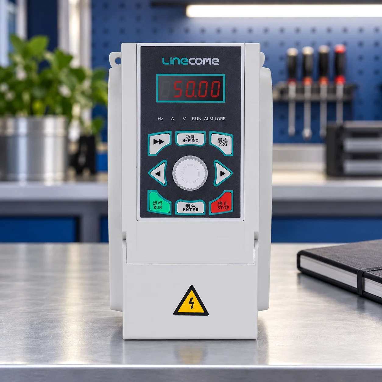
Mechanical shaft power is related to torque and angular speed by P = Tω. Reducing speed reduces mechanical output power at constant torque. However, the current needed to develop that torque does not fall in direct proportion to speed. Electrical losses and reduced ventilation can therefore remain important even when the process consumes fewer shaft kilowatts.
As an illustrative mechanical calculation, 30 N·m at 1,500 rpm represents approximately 4.71 kW of shaft power. The same torque at 300 rpm represents approximately 0.94 kW. This is not an electrical-input calculation and does not predict motor temperature. It shows why a low-kilowatt operating point can still be a substantial torque duty.
Winding resistance produces heating related to current squared. At the same resistance, increasing current by 20% increases the corresponding resistive loss by a factor of 1.2², or 1.44. This simplified relationship is described in OpenStax’s electrical energy and power chapter. Actual motor losses also include other effects, and winding resistance changes with temperature; do not turn this example into a complete thermal model.
Check whether the motor cools itself adequately
A shaft-mounted fan generally slows with the motor. At prolonged low speed, reduced airflow can limit the motor’s ability to reject heat. Enclosure type, mounting, ambient conditions and the motor’s construction determine the significance. A separately powered fan can provide cooling independent of shaft speed, but its suitability and required airflow need confirmation for that motor.
The DOE’s motor-driven systems guidance identifies poor cooling as a possible limitation when slowing equipment. Use motor-supplier torque-versus-speed capability and cooling information rather than a universal minimum-frequency rule. Two motors with the same rated power may have different permitted continuous low-speed duties.
Inspect external cooling paths with the equipment safely isolated where required. Look for blocked air inlets, accumulated dirt, damaged fans and recirculated hot air. Confirm the direction and condition of a separately powered cooling fan and whether its failure is detected. Cleaning or restoring ventilation may solve a cooling defect, but it does not increase the motor’s original duty rating.
Identify constant-torque and variable-torque duty
A conveyor, extruder or loaded mixer may require substantial torque at low speed. A suitable centrifugal fan or pump often requires less torque as speed decreases, although the actual system curve and operating point still matter. Do not apply a fan’s reduced-load assumptions to machinery that must deliver near-rated torque while creeping.
Describe the driven load across the complete speed range. Include starting torque, material condition, pressure, viscosity, gearbox behavior and any mechanical binding. A machine that has become harder to turn may impose a new thermal demand even though its speed setpoint has not changed. Compare present operating conditions with the original selection assumptions.
| Observed condition | Question to investigate | Evidence to obtain |
|---|---|---|
| Hot only during long low-speed runs | Is continuous low-speed torque compatible with available cooling? | Motor duty curve, current trend and run duration |
| Hot after repeated starts | Does the production cycle accumulate heat? | Starts per hour, load, ramp behavior and cooling intervals |
| Temperature rises after maintenance | Did cooling, motor data or the mechanical load change? | Before/after configuration and inspection record |
| Drive alarm but motor appears normal | Is the alarm related to drive cooling instead? | Exact fault definition, enclosure condition and drive fan status |
| Different measurements disagree | Are the same location and temperature quantity being compared? | Sensor type, measurement point and instrument method |
The table is a decision aid rather than a fault-code chart. Preserve the original alarm details and document the inspection method. Several conditions can coexist, such as restricted airflow and a heavier-than-planned mechanical load.
Verify motor data and the thermal protection arrangement
Confirm nameplate voltage, current, frequency, rated speed and the actual motor connection. Check that the drive’s configured motor data matches the installed motor. A replacement motor may have different ratings even when the mechanical frame appears identical. Incorrect entries can affect control and protection behavior.
Determine how motor protection works at low speed. A thermal model may depend on correct parameter entries and assumptions about cooling. Winding sensors provide different information and need the correct interface, type and alarm response. Ask the supplier whether the protection arrangement covers the intended speed range, separately powered ventilation and repeated duty.
Do not simply increase the overload setting or reset the thermal model after a trip. Investigate why the protective estimate or sensor reached its limit. Confirm the permitted restart condition. A motor can retain heat during a short stop, and an immediate restart may begin from a much warmer condition than the first test of the day.
Review control settings without treating them as universal cures
Excessive voltage boost or unsuitable low-speed control settings can increase current and heating. Too little effective torque can also produce poor operation. Confirm the control mode, motor identification procedure and parameter guidance for the exact drive. A setting copied from another application may not suit a different motor or load.
Switching frequency can affect drive losses, acoustic behavior and motor-related effects, but changing it is not a substitute for a thermal assessment. Follow the drive and motor supplier’s recommendations, including any current derating. Cable length, insulation suitability and output filtering may need separate review; they should not be guessed from the motor’s frame size.
Where an encoder or other feedback is required to achieve the intended low-speed performance, confirm the complete arrangement. Better speed regulation does not automatically create more cooling capacity. Likewise, a drive advertised for vector control does not prove that an ordinary self-cooled motor can deliver continuous rated torque arbitrarily close to zero speed.
Consider mechanical changes and cooling options
Possible solutions include restoring the original cooling path, reducing continuous torque, revising the operating sequence, adding an approved independent cooling arrangement or selecting a motor designed for the required inverter-fed duty. The correct choice depends on the measured cause and production requirement. A fan upgrade cannot correct an electrical connection error or a binding gearbox.
Changing the transmission ratio may allow the motor to run faster while the driven machine runs slowly. Evaluate motor torque, gearbox rating, efficiency and maximum machine speed together. Do not adopt a ratio change solely to improve motor ventilation without checking the rest of the mechanical operating range.
Upsizing a motor also needs engineering review. Starting and running characteristics, drive current capability, mechanical fit and protection settings may all change. A larger motor is not automatically a better low-speed motor. Ask for a documented capability match rather than choosing by the next available kilowatt size.
Run a controlled thermal acceptance test
Agree test conditions with the equipment owner and supplier. Include representative load, the lowest intended continuous speed, ambient conditions and the actual repeating cycle. Log current, speed, temperature information and cooling status over an adequate period determined by the test plan. A short unloaded run cannot establish thermal suitability for a long loaded shift.
Record where each temperature is measured and which limit applies. Compare winding-sensor information, housing measurements and protection-model estimates according to their intended purpose. Stop the test if limits or safe operating conditions are exceeded. Do not bypass protection to obtain a longer data trace.
Once a correction is made, repeat the relevant conditions and retain the results. Document permitted speed, load, duty and cooling requirements in the handover. If the operating process changes, review those limits rather than assuming the original acceptance covers every future production pattern.
What to include in a LINECOME application enquiry
Provide the motor nameplate and cooling arrangement, exact drive model, supply details, current and speed records, alarm history, load description and required hours at low speed. Include the enclosure environment and any temperature-sensor information. Ask for a specific review of continuous low-speed torque and the protection configuration.
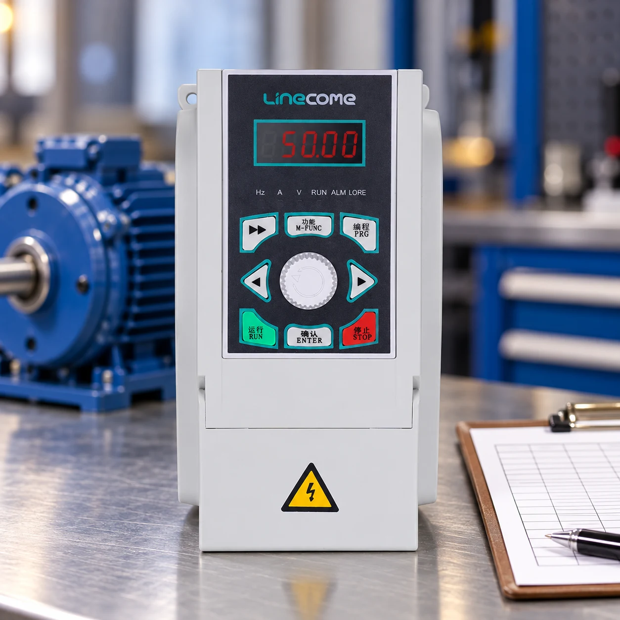
The LINECOME LNC820 range can be discussed once the motor current and operating duty are established. Compare alternatives through the product hub, and use the cabinet-planning guide for drive ventilation and site conditions. The article’s illustrations retain the website drive’s appearance; they do not establish a motor temperature rating or show a completed installation.
Further learning and frequently asked questions
The Engineering Mindset’s independent VFD explanation introduces the electrical power stages and adjustable-frequency operation. It provides background to the control discussion, while the motor’s documented duty and site measurements remain essential.
Watch the VFD explanation on YouTube.
What is a safe minimum frequency for every motor?
There is no universal value. The permitted continuous range depends on motor design, cooling, torque, control method and duty.
Does low output current prove that the windings are cool?
No. Temperature also depends on cooling, prior loading, operating duration and other losses. Use the appropriate thermal information.
Will a larger VFD prevent motor overheating?
Not by itself. A larger drive does not increase the motor’s cooling capacity or change its permitted continuous torque-speed duty.
Can a separate cooling fan solve the problem?
It may help when insufficient ventilation is the identified cause, but its design and protection must suit the motor. Other electrical or mechanical causes still require correction.


