




Motor control panel breaker coordination begins with the supply conditions, available fault current, motor-starting duty and the complete protective arrangement. It cannot be settled by choosing a breaker whose ampere rating looks close to the motor current. Ask for evidence covering interruption capability, the panel or combination short-circuit rating, overload protection and the required selectivity with upstream devices. This RFQ checklist helps industrial buyers collect the right information without claiming that a standalone breaker establishes the performance or certification of the assembled panel.
Start with the protection question you need answered
The phrase “breaker coordination” can mean several things. One buyer may be asking whether a downstream fault can be cleared without stopping the whole facility. Another may need a verified motor-controller combination, while a third is concerned about nuisance trips during acceleration. State the problem explicitly before asking suppliers to propose devices.
Create separate acceptance questions for normal load, starting, motor overload and short-circuit conditions. Also define the consequences of losing a branch circuit or the main supply. That approach prevents a quotation from appearing complete because it contains a large breaker, while the actual requirement for selective operation or a documented assembly rating remains unanswered.
Keep the important ratings separate
A breaker’s continuous-current information, interrupting capability and trip characteristics describe different aspects of its use. A panel’s short-circuit current rating concerns the assembly. Selectivity concerns which protective device operates for a given fault. Motor overload protection addresses another duty and must be identified in the selected arrangement.
UL’s combination motor-controller guidance describes ratings for specified combinations of components. Its North American terminology should be applied within the relevant project framework. It does not mean that an unrelated breaker, contactor and starter can be combined freely and inherit the strongest rating printed on any one component.
Give the supplier a complete input schedule
| Input | Why it changes the review | What the quotation should identify |
|---|---|---|
| Supply voltage and frequency | Ratings and curves apply under stated conditions | Exact applicable device data |
| Available fault current | Establishes the fault level the assembly must address | Study basis and rating comparison |
| Motor nameplate and load | Defines running and starting requirements | Starter method and protection roles |
| Starting profile | Helps evaluate unwanted operation during acceleration | Assumed current-time envelope |
| Upstream protective device | Determines the coordination interface | Manufacturer, model and settings |
| Required continuity | Defines the selectivity objective | Scope and limits of the study |
| Installation conditions | Can affect thermal performance and enclosure design | Ambient and derating assumptions |
Use the table as an enquiry schedule. It does not provide trip settings or conductor sizes. Those require project calculations, the applicable electrical rules, the equipment data and review by a qualified designer. If an input is unknown, identify who must obtain it before final selection.
Establish the available fault current at the panel
Ask the site electrical engineer for the fault-current information at the intended installation point, with its assumptions and revision. A transformer rating by itself is not a complete answer. The supply arrangement and the path to the panel matter, and later changes can invalidate an earlier assessment.
UL’s machinery SCCR questions and answers explains why available fault current and the equipment rating must be considered together. Use the relevant standard and jurisdiction for the actual project. If the study has not been supplied, record the selection as conditional; do not turn a missing site value into an unsupported assurance that the proposed cabinet is suitable.
Identify the exact breaker and trip unit
Require the full catalogue reference, frame information, poles, rated voltage, trip-unit type and any adjustable functions. Record the proposed settings separately from the device’s maximum capabilities. A frame description alone may not identify the characteristic that governs a coordination assessment.
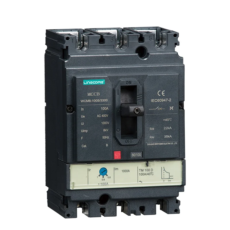
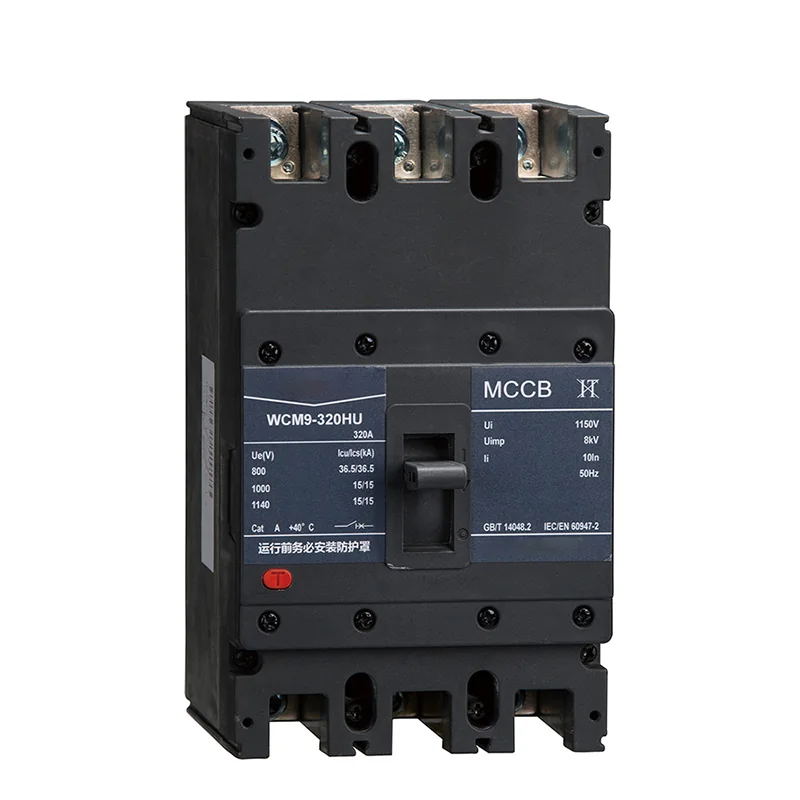
Photographs of the LINECOME WCM8 moulded case circuit breaker and the related WCM6 and WCM9 families illustrate different products. They are useful for identifying what is being quoted, but the markings visible on a photograph do not establish every orderable variant or an assembly approval. Ask for the exact supplied unit’s datasheet and supporting documentation.
Match the review to the motor-starting method
A directly started motor, a soft starter and a VFD present different operating conditions to the branch protection. Tell the supplier which method is used and whether bypass or an alternate operating path is included. Provide the expected starting sequence and any relevant manufacturer constraints rather than treating all motor circuits as interchangeable.
For a soft-starter bypass arrangement, include every intended current path in the review. For a drive installation, use the drive manufacturer’s specified protective-device conditions. Do not copy a breaker selection from an equal-power motor circuit with a different starting method. The complete equipment documentation should explain why the proposed protection fits the actual arrangement.
Ask who provides motor overload protection
List the device or function responsible for motor overload protection and identify how it senses the motor. Where a starter or drive provides an electronic overload function, obtain the settings basis and applicable limitations. Where an external device is used, include its reference and integration in the drawing.
Do not assume that a breaker automatically fulfils every motor-protection requirement because it has a thermal trip characteristic. The selected combination and applicable rules determine the roles. Make the quotation name the overload function explicitly, especially when alternative modes could route current around the normal sensing path. This makes later inspection and maintenance much less ambiguous.
Request actual coordination evidence
Ask the designer to identify the relevant curves, manufacturer tables or verified combinations, together with their conditions of use. A statement such as “breakers are coordinated” should identify which upstream and downstream devices were considered and over what range. Distinguish a full study from a preliminary screening.
If selectivity is required for business continuity, define its scope. Is the objective to keep unrelated branches operating during an overload, a particular fault range, or every considered fault up to the available level? There may be limits to what a proposed combination can demonstrate. Record those limits so the owner can make an informed decision about continuity and cost.
Treat substitutions as changes to the evidence
A replacement breaker may fit mechanically and have a similar current marking while differing in its trip characteristic or documented combinations. The same issue can arise when a contactor, overload device or starter is substituted. Require the builder to assess whether the change affects the study and assembly documentation.
Keep a controlled bill of materials linked to the approved drawings. Record the final protective-device settings and any conditions required by the supporting data. If a supplier proposes an alternative during procurement, ask for the revised evidence before approving it. A previous coordination record should not remain in the handover package as though it still describes an altered assembly.
Check construction and records at the factory
Compare installed references and settings with the approved schedule. Inspect labels, access, terminal identification and the construction checks required by the applicable assembly procedure. Confirm that the final documentation shows the device actually fitted. Photographs can supplement the record, particularly for inaccessible labels, but should not replace the required test reports.
A normal factory power-on test does not reproduce a short-circuit test and should not be described as one. Likewise, manually operating a breaker does not prove selectivity. Identify which properties are supported by manufacturer data, design assessment and prescribed construction tests, and which functional checks were actually witnessed. Keep those forms of evidence distinct in the acceptance report.
Plan maintenance access and change control
Protection remains meaningful only if the final settings and component references can be recovered later. Provide a settings schedule with controlled access, clear device labels and a process for recording authorized changes. Explain how the maintenance team should evaluate a proposed replacement or a change in motor duty.
Service work must follow a hazardous-energy control procedure. NIOSH’s guidance covers prevention of unexpected energization and release of stored energy. A coordination study is not permission for unqualified live adjustment. Energized diagnostics, maintenance isolation and protective-device setting changes each need appropriate authorization and competent personnel under the site’s procedures.
Close the RFQ with named deliverables
A useful enquiry requests the exact devices, drawings, settings basis, rating evidence, coordination scope, assumptions, test documents and remaining site inputs. Ask the supplier to distinguish included work from work that must be supplied by the owner’s engineer. That avoids discovering after delivery that both parties expected the other to produce the fault study.
For background, read the site’s drive installation and branch-protection articles alongside the broader motor-control explanation. They help separate equipment selection from wiring and commissioning tasks. When enquiring about WCM8 products, provide the application data and request the relevant model documentation; do not infer international certification, tested combinations or site suitability from a catalogue photograph or a family-level description.
Educational video: what a breaker protects
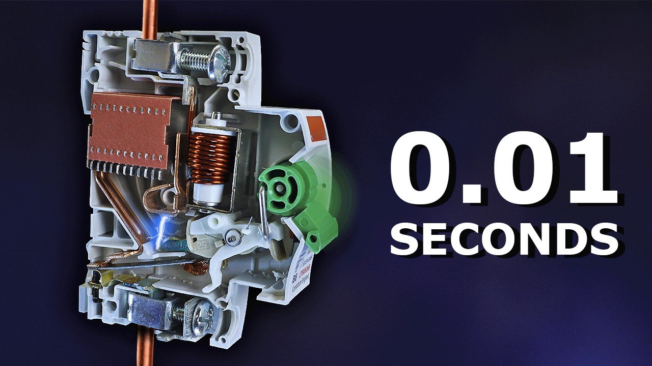
Video: The Engineering Mindset. Watch Why Circuit Breakers DON’T Protect People (electric shocks) on YouTube.
The Engineering Mindset explains overload and short-circuit protection using a small circuit breaker. This is background on operating principles, not a coordination study for the WCM range or a guide to selecting industrial trip settings. The project designer must use the exact equipment data.
Related LINECOME guides
- How a Variable Frequency Drive Works — From Line Power to Motor Speed
- VFD Installation — Field Wiring, Grounding, and Commissioning Checklist
- 6 Amp 230 V VFD Breaker Size — Branch Protection Checklist for Small Drives
Frequently asked questions
Does a high interrupting rating establish the entire panel rating?
No. The assembly must be assessed under the applicable method. The ratings and conditions of the other components and their specified combinations still matter.
Can a factory functional test prove selectivity?
An ordinary functional test cannot establish fault-current selectivity. That question needs appropriate curves, manufacturer data, assessment or testing covering the specified devices and conditions.
What happens if the upstream breaker changes later?
Review the coordination interface and relevant assumptions again. Retain the revised device reference, settings and study so the record continues to describe the installed system.


