




A permanent magnet motor VFD autotune identifies motor characteristics for the drive’s control model; it does not prove that the machine is ready for production. Before tuning, confirm the exact motor type, enter verified motor data, select the manufacturer-approved stationary or rotating procedure, and establish safe mechanical conditions. Afterward, verify direction, feedback, current and operation under progressively applied load. A successful tune message is one checkpoint in that sequence, not the acceptance result. This guide explains what buyers and commissioning engineers should prepare, observe and retain when handing over a permanent-magnet motor and drive package.
Define the motor-and-drive combination first
A permanent-magnet synchronous motor is not interchangeable with an induction motor simply because both have three power leads and the same power rating. Rotor construction, back electromotive force, feedback and the control algorithm affect whether a drive can operate the motor correctly. Confirm the motor manufacturer’s model designation, whether the rotor is surface-mounted or interior-magnet construction, and which motor types the particular drive firmware supports. Do not choose the motor category by guessing from the enclosure.
The IIT Roorkee Virtual Labs PMSM explanation describes the permanent-magnet rotor and synchronous operation. That establishes the machine principle; actual commissioning values still come from the supplied motor documentation. A photograph, motor efficiency class or horsepower figure cannot supply those values.
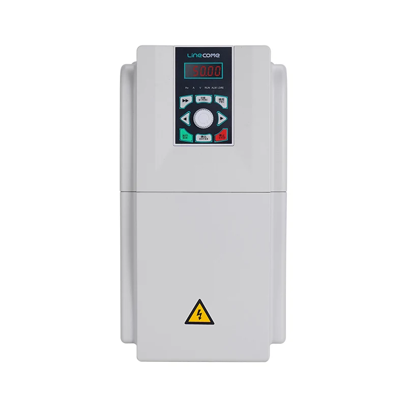
LINECOME lists the LNC860E permanent-magnet synchronous VFD for synchronous motor applications. Its catalogue describes open-loop and closed-loop vector options and feedback choices. Confirm the exact ordered drive, firmware, feedback card and motor combination with the supplier. This article does not assign parameter numbers, promise compatibility with every PM motor, or replace the delivered programming manual.
Build a motor data sheet before opening the tuning menu
Create one controlled record combining the motor nameplate, detailed electrical data sheet, drive order code and application requirements. Resolve missing information with the motor supplier before energization. Values copied from another motor of similar size can produce a plausible-looking setup that behaves poorly under load.
Record rated current, voltage, power, speed, frequency and pole information using the units expected by the drive. Where required, obtain winding resistance, inductance and back-EMF data together with their measurement definitions. A line-to-line value and a per-phase value are different descriptions. Likewise, electrical frequency and shaft speed should not be entered into each other’s fields. Avoid converting unfamiliar units without a documented convention from the relevant manual.
The following is a document-control checklist, not a universal list of editable parameters. Its evidence requirements reflect the need for a motor-specific model and application limits.
| Information to resolve | Evidence to request | Reason to hold the test |
|---|---|---|
| Motor family and rotor construction | Motor model and manufacturer’s data sheet | Drive support for that motor type is unconfirmed |
| Rated electrical and speed data | Legible nameplate plus matching technical data | Units or nominal values disagree |
| Back-EMF and motor constants, when required | Definitions supplied for the exact winding | A value has been estimated from a different motor |
| Feedback arrangement | Encoder or resolver specification and drive card details | Interface or alignment method is unresolved |
| Mechanical operating envelope | Machine speed, rotation and load constraints | Tuning movement could damage equipment |
| Tuning procedure | Manual for the delivered drive and firmware | Only a generic internet procedure is available |
Choose a tuning method that the machine can safely support
Stationary tuning and rotating tuning are not equivalent tests. What each identifies, which constants must already be known and what movement can occur depend on the drive. Some identification routines energize the motor without sustained rotation; other routines deliberately move or rotate the shaft. Read the procedure and warnings for the specific equipment before deciding that a coupled load may remain attached.
A rotating routine may require an unloaded or uncoupled motor. That requirement matters for pumps, compressors, gear trains, brakes and machines with restricted travel. If uncoupling is impractical, obtain the drive supplier’s approved stationary method and its limitations. Do not simply run the rotating procedure with the machine restrained. A brake holding the shaft can change the test condition and may expose the drive or machine to unacceptable forces.
The test plan should state who controls the start command, what movement is expected and how the work area is cleared. It should also identify the return-to-service sequence. The CCOHS lockout/tagout guidance explains energy isolation and the distinction between controls and isolating devices. Apply the site’s equipment-specific procedure and local requirements; a keypad stop is not an isolation method.
Prepare the installation without confusing tuning with wiring checks
Verify the motor cable route, protective earth, terminations, screening and feedback wiring against approved drawings. Complete insulation checks using the equipment manufacturers’ procedures, with sensitive electronics disconnected where required. Do not apply an insulation tester through the drive or feedback electronics. Record the actual cable arrangement because changing the connected motor circuit can affect the conditions represented by the saved identification data.
Check the state of output contactors and any switching arrangement. The motor must be connected as required during identification, and the drive must not be subjected to unauthorized output switching. Resolve remote starts, automatic restarts and process commands before the test. A PLC request arriving halfway through commissioning should not unexpectedly change the command source or initiate production motion.
For the installation evidence that precedes this work, use the separate VFD installation and grounding checklist. This autotune checklist starts with an electrically verified installation and focuses on identification and acceptance, rather than repeating the complete wiring procedure.
Run identification and preserve the result
Back up the configuration before making changes. Enter the verified motor data, select the approved motor and control modes, and then check the limits applicable to the identification operation. Follow the manual’s motor-temperature and load conditions. Do not use a cold-resistance assumption for an already heated machine unless the manufacturer explicitly permits it.
During the routine, record the selected tuning mode, completion indication, fault history and any movement or abnormal sound. A failed routine should trigger diagnosis of the conditions: incorrect motor category, missing data, an unsuitable load state, feedback problems or an incomplete motor connection. Save the exact code and sequence before resetting anything. Repeated attempts without a changed hypothesis add heat and obscure the original evidence.
After a reported success, save the resulting configuration and compare it with the pre-test backup. Retain both the entered data and the identified values that the drive makes available. If a value is implausible or the routine produces inconsistent results, stop and ask the equipment supplier to review the record. Do not replace an unfamiliar identified value with a preferred number simply to clear an alarm.
Prove direction, feedback and controlled motion
Use the manufacturer’s permitted first-motion procedure in a cleared test area. Confirm actual shaft direction against the machine requirement rather than relying only on a positive speed display. With closed-loop control, verify the relationship between motor phase sequence, feedback direction and the prescribed alignment or offset procedure. A drive can complete part of its setup while a feedback issue remains.
Start with conditions that let the team observe the machine safely. Check whether the shaft follows the command smoothly, whether measured speed is credible and whether current behaves consistently. Do not solve unstable motion by immediately increasing current limits or gains. Establish that the entered data, tuning result, feedback and mechanical condition agree first.
For background on how the inverter and motor interact, see how a variable frequency drive works. The NPTEL lecture below provides further teaching on sinusoidal permanent-magnet brushless drives. It explains the control context; it is not an LNC860E setup tutorial.
Video by NPTEL IIT Delhi. Watch Sine Wave Permanent-Magnet Brushless Motor Drives on YouTube.
Add load in stages and test the real operating envelope
A no-load test cannot demonstrate production torque, thermal behaviour or recovery after disturbances. Agree a staged load plan with the machine owner. At each permitted operating point, record command speed, actual speed, current, process response and any relevant temperature observations. Include the low-speed and load-change conditions that actually matter to the application, rather than only a convenient midrange run.
Confirm acceleration and stopping behaviour within the machine limits. Where the load can drive the motor, assess the stopping and regenerated-energy arrangement with the drive supplier. A successful identification routine does not size a braking system or authorize overspeed. Keep mechanical restraints, protective functions and process interlocks within their approved design throughout testing.
Acceptance should also cover command-source changes and the specified response to lost feedback, lost communications and power restoration. Simulate faults through approved methods rather than creating damaging electrical conditions. Identify which faults require a deliberate reset and whether restarting could expose personnel or the process to danger. Record the result of each test, including tests deliberately deferred.
Diagnose failed acceptance before changing the model
If the motor trips only after load is applied, preserve the fault snapshot and compare the failing point with the unloaded result. Check actual load, acceleration demand, current limits, cooling and motor data. If motion is unstable immediately, investigate the control mode and feedback arrangement before attributing everything to mechanical load. The complementary VFD overcurrent troubleshooting guide helps organize current-related evidence without turning every trip into an autotune problem.
A motor replacement, winding change, feedback change or relevant drive replacement should trigger a review of the commissioning record. Whether identification must be repeated depends on the equipment instructions and the change. Treat a copied parameter file as a starting record to validate, not proof that the replacement machine has passed acceptance.
What to request with the drive quotation and handover
Send the supplier the motor data sheet, intended speed and torque envelope, feedback details, cable information, environmental conditions and permitted tuning movement. Ask for the supported commissioning method, required motor constants, applicable manuals and evidence of the proposed drive-and-motor match. Specify who is responsible for the initial setup and who signs off the loaded test.
The handover package should contain the final drive identity, firmware, motor identity, approved settings, tuning record, fault log and staged test results. Include a retrievable backup, restoration instructions and a clear list of unresolved items. This makes future maintenance repeatable and prevents a later technician from confusing a saved factory configuration with the settings actually accepted on the machine.
Frequently asked questions
Can an induction-motor VFD autotune be used for a PM motor?
Only if the specific drive supports that PM motor type and the correct approved mode and procedure are selected. An induction-motor identification routine is not a substitute for confirming PM compatibility and entering the required motor data.
Does stationary tuning guarantee that the shaft cannot move?
Do not assume so. Expected movement and precautions depend on the manufacturer’s routine. Establish safe mechanical conditions and follow the exact equipment instructions before energizing the motor for identification.
Is a successful autotune enough to release the machine?
No. Verify direction, feedback, controlled movement, loaded operation and the specified protective responses. Save the final settings and test evidence before signing the commissioning handover.


