




A multi pump control cabinet should implement a clearly defined operating sequence: which pump leads, when another pump assists, how standby equipment takes over, and what happens when a pump or sensor fails. Acceptance testing must prove these behaviours and the return to normal operation. Start by distinguishing duty/standby from duty/assist, because the permitted simultaneous operation and hydraulic requirements differ. Then agree a cause-and-effect schedule and test it at the factory with safe simulation, followed by site checks using the actual pumps, instruments and pipework.
Define the operating arrangement in plain language
In a simple duty/standby arrangement, one pump normally meets the specified duty while another is available as backup. In duty/assist operation, an additional pump can run when demand requires it. Alternation changes which pump leads, often to distribute use. These functions can coexist, but they are not interchangeable descriptions of the same sequence.
Ask the process designer to describe normal demand, high demand, low source level and pump failure. State how many pumps may run together and whether that changes under an abnormal condition. A label saying “two-pump control” does not answer these questions. The cabinet and the hydraulic system must be designed around the same operating philosophy.
Verify the product scope against the required sequence
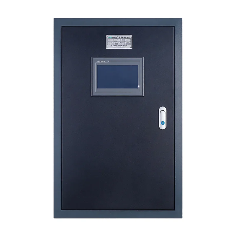
The LINECOME pump control cabinet page describes single- and dual-pump arrangements, including alternating duty and certain dual-pump functions. Confirm which features are included in the actual quotation, the motor ratings, sensor arrangement and operating modes. A family-level description is not a complete control narrative for every order.
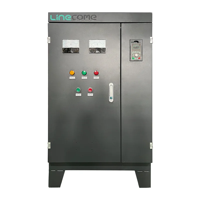
Ask whether the offered system uses contactor control, variable-speed control, a PLC, or another controller. Photographs of related cabinet types help explain the available hardware categories, but they do not establish the configuration of the supplied pump panel. Require a bill of materials and an approved sequence linked to the ordered cabinet reference.
Make a cause-and-effect table before programming
| Condition | Decision to specify | Evidence to collect |
|---|---|---|
| Normal demand begins | Select the eligible lead pump | Command, feedback and selected lead |
| Demand ends | Stop using the approved sequence | Stop response and final state |
| Higher demand occurs | Start assist only if permitted | Staging sequence and hydraulic site result |
| Running pump fails | Exclude it and assess standby availability | Fault alarm and takeover record |
| A pump is under maintenance | Prevent automatic selection | Exclusion indication and command check |
| Sensor becomes invalid | Enter the agreed fallback or stop state | Fault detection and recovery test |
| Power returns | Apply the approved restart policy | Recovery record and operator indication |
The table is a planning framework, not a universal control program. Fill in thresholds, delays and priorities from the project design. Requirements for sewage level control, water-supply pressure control and critical services may differ. Do not copy a high-level response from one application into another without checking the consequences.
Use public specifications as examples, not automatic settings
The Southland District Council bylaw document includes an example of a pump-station control specification with standby and level-related functions. It demonstrates how an owner can define operating behaviour and alarms. It is not a current universal design code or a source of settings for every pump panel.
For your project, identify the applicable current requirements and obtain the designer’s sequence. Where the design calls for independent backup sensing or special abnormal-condition operation, show those functions in the drawings and acceptance procedure. Treat an older public specification as background evidence, while the approved project documents remain the acceptance reference.
Decide when and how lead alternation occurs
Alternation can be requested after a completed cycle, according to accumulated run time, at a scheduled opportunity, or by an operator under defined conditions. Ask what triggers it and whether a transfer may occur while pumping. Specify how the system handles a pump that is unavailable when its turn arrives.
Factory tests should show more than the lead indicator changing. Simulate several demand cycles and verify the actual selection and commands. Include a disabled pump and confirm that the healthy pump remains eligible. Record whether a power interruption preserves or resets the alternation state, and make that behaviour consistent with the operating instructions.
Prove standby takeover without creating a real failure
Use an agreed fault simulation to make the running pump unavailable. Observe the fault indication, command removal, selection of eligible standby equipment and the conditions needed to request a replacement start. Confirm whether the system waits for a feedback state, applies a delay or requires operator intervention, as specified.
Do not assume takeover is always immediate or always safe. The process, motor-starting constraints and hydraulic conditions determine the sequence. If the standby pump is also unavailable, test the resulting alarm and system state. A useful acceptance record shows both the successful backup path and the condition in which no eligible pump remains, so operators know the limits of redundancy.
Exclude equipment that is under maintenance
Define how a pump is marked unavailable and how that status appears to local and remote operators. The control system should not continue selecting equipment that has been removed from automatic service. Verify that restoration to service follows the agreed procedure and does not cause an unintended start merely because a maintenance selector is moved.
Maintenance exclusion is a control function, not a substitute for energy isolation. NIOSH hazardous-energy guidance explains the need to prevent unexpected energization and stored-energy release. A software unavailable flag cannot protect someone servicing the pump. The site must use the appropriate physical isolation and verification procedure for all relevant energy sources.
Verify assist staging against the hydraulic system
If two pumps may run together, specify what demand condition permits the second start and how the system returns to one-pump operation. Avoid uncontrolled switching around a single threshold. Delays, separate start and stop conditions, or other control measures must come from the application design rather than an arbitrary rule copied from another installation.
The DOE pumping-system sourcebook explains the importance of system-level pump selection and operation. Use the pump curves and system design to assess simultaneous operation at the site. A factory simulator can demonstrate logic, but it cannot prove that the actual pipework, valves and pumps produce an acceptable operating condition.
Separate command, feedback and proof of pumping
A run command means the controller has asked a pump to operate. A contactor or drive feedback signal can indicate an electrical state. Neither necessarily proves the required flow or pressure. Decide which feedback the application needs and what should happen if the expected response does not appear.
Test command and feedback mismatch using approved simulation. Confirm the alarm wording and whether the controller tries another pump, stops, or waits for intervention. If no flow instrument is installed, avoid screen messages that claim verified flow. The operator should understand what each indication actually measures and where further diagnosis is required.
Test sensors and abnormal combinations
Simulate the normal range and agreed failure conditions of the level or pressure input. Verify scaling, engineering units and any documented invalid-signal behaviour. Check that a tank-full condition is not mislabelled as source-water loss, and that a high-demand condition cannot silently override a protective inhibit unless the approved design explicitly requires it.
Include combinations that reveal priority errors. For example, present demand while one pump is unavailable, then simulate a fault on the remaining pump. Test local and remote mode changes where those modes exist. Record the expected result before applying the scenario. A test that invents its acceptance criterion after seeing the outcome provides weak evidence.
Include power recovery and remote control
Agree what happens after the main or control supply returns. The system may need to re-evaluate demand, pump availability, faults and start permissions before issuing commands. Verify whether starts are sequenced and how the operator is informed. Do not assume that restoring power should simply resume every command that existed before the interruption.
For remote systems, check loss of communication separately from local control failure. Define whether local automatic operation continues, stops or enters another mode. Test the return of communications and any stale commands. The handover should explain which functions depend on the remote link so the site team does not confuse an unavailable screen with a failed local pump controller.
Split factory and site acceptance clearly
At the factory, verify construction records, device references, input/output mapping, mode logic, alarms and the agreed simulated scenarios. Retain the tested program and settings revisions. Record any temporary links or forced values and confirm their removal before shipment. Use a named punch list for unresolved issues.
At the site, verify the actual sensor identities, motor rotation by the approved method, valve arrangement, hydraulic performance and real feedback paths. Demonstrate the operating scenarios that could not be represented at the factory. The site’s pump PID and drive commissioning articles provide related background, but they do not replace the project-specific acceptance procedure or the pump manufacturer’s installation limits.
Educational video: the pump side of the system
Video: The Engineering Mindset. Watch How do centrifugal pumps work? on YouTube.
The Engineering Mindset explains centrifugal-pump operation and the relationship between components. This neutral introduction helps a project team understand why logic testing and hydraulic testing are separate tasks. It is not a model-specific demonstration of the LINECOME cabinet or a validation of a two-pump sequence.
Related LINECOME guides
- How a Variable Frequency Drive Works — From Line Power to Motor Speed
- VFD PID Control for Constant-Pressure Pumps: Setup and Tuning
- VFD Hoist Commissioning Checklist: Brake, Load and Acceptance Tests
Frequently asked questions
Are duty/standby and duty/assist the same?
No. Duty/standby normally provides backup capacity, while duty/assist permits an additional pump to meet demand. The exact permitted simultaneous operation must be stated in the control narrative.
Does alternating the lead prove both pumps are healthy?
No. Alternation proves a selection function. Health requires the appropriate feedback, protective status and operating checks for each pump, including site hydraulic verification where required.
Can a factory test prove the full pumping system works?
No. It can prove the agreed cabinet functions and simulations. Actual field wiring, instruments, pumps and pipework require site checks and a documented acceptance record.


