




PLC analog input noise should be traced from the measured process to the raw input value before a software filter is increased. Compare the transmitter indication, the receiving module’s raw counts and the displayed engineering value during the same operating event. Then test a documented boundary with a suitable reference source. A smooth screen does not prove a healthy signal, and an unstable screen does not automatically mean the sensor is defective. This guide concerns PLC receiving channels in industrial cabinets; changes to live circuits and machine behavior require qualified personnel and an approved test plan.
Establish what is actually moving
Begin with the process, rather than the cabinet. Pressure pulsation, a vibrating probe, an intermittently grounded thermocouple or an unsuitable measuring range can produce a changing signal that accurately represents a problem outside the PLC. Ask whether the local transmitter display moves at the same time. Check a second independent process indication where one exists. Do not declare the PLC noisy merely because two instruments use different averaging periods.
Capture a trend with timestamps and useful context: raw input, scaled value, sensor diagnostic state, machine operating mode and the event believed to trigger the disturbance. Record the sampling and display update periods. A screenshot taken after an event cannot reveal whether a valve movement preceded or followed the signal change. Agree on the observation window before repeating a production sequence.
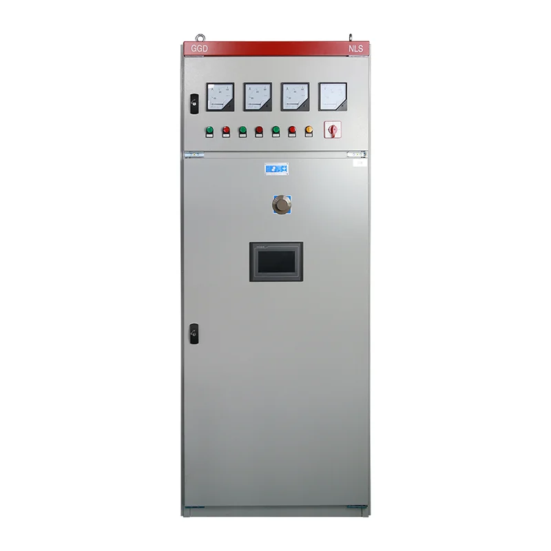
The PLC cabinet overview explains the wider architecture. For this investigation, identify one channel by module, terminal, field tag and drawing revision. A generic cabinet description cannot establish how that particular channel is referenced or protected.
Separate three layers of evidence
Read the raw input value without changing the application. If raw counts remain stable while the engineering display jumps, examine scaling, data types, recipe selection and the display’s source tag. Check whether another routine writes to the same value. A signed conversion or a changing calibration offset can resemble electrical interference but requires a software correction.
If raw counts fluctuate, compare them with an appropriately measured field signal. The test instrument must suit the signal and circuit; inserting an ammeter can interrupt a current loop, while an incorrectly connected voltage meter can create a fault. Define permitted connection points, expected interruption and temporary control arrangements in the work instruction. Never improvise measurements on exposed energized power wiring.
If both the local process indication and the raw value move together, inspect the process and transmitter before rerouting cables. If only the receiving channel moves, continue along the signal path. This comparison narrows the investigation; it does not by itself prove which component has failed.
Use a boundary test to divide the problem
With the process secured, a competent instrument technician can disconnect the field circuit under the approved procedure and apply a compatible reference signal at the receiving boundary. Confirm current versus voltage mode, polarity, sourcing versus sinking arrangement and allowable input limits before connecting anything. Retain the actual module manual alongside the drawing.
A stable reference at the module terminals indicates that the receiving side can measure that source under those conditions. It does not validate the full field cable or the transmitter. Move the test boundary outward in controlled stages where practical, recording what remains connected. Conversely, a reference that is unstable at the module calls for reviewing channel configuration, references, supply quality and module condition before blaming the field wiring.
Do not short an arbitrary input to earth as a universal test. Some inputs need a defined bias path; others are current inputs with an internal shunt or have isolation arrangements that must be preserved. NI’s field wiring and noise guidance explains why source grounding and input configuration must be considered together. Its DAQ examples illustrate principles, rather than serving as terminal instructions for every PLC.
Match observations to the next check
The following table is a qualitative diagnostic worksheet. It applies the source-and-receiver distinction described above; it does not prescribe manufacturer limits or claim a fault from a single symptom.
| Observation | First boundary to examine | Evidence to retain |
|---|---|---|
| Raw value stable, display unstable | Application scaling and tag ownership | Raw trend beside display trend and active recipe |
| Reference stable locally, field signal unstable | Field cable, transmitter and process | Test boundary, connected equipment and operating state |
| Several channels jump together | Shared reference, module supply and common event | Channel group, supply trend and event timestamps |
| Disturbance follows a contactor operation | Coupling path and approved suppression arrangement | Switching event, cable route and component identification |
| Disturbance appears only with a drive running | Routing, bonding and receiver limits | Drive state and channel trend, without removing protective earth |
| More filtering smooths the value but delays response | Measurement and control response together | Before-and-after trend and alarm response test |
Inspect routing without inventing a shielding rule
Compare the installed route with the approved arrangement. Look for a signal cable sharing a duct with motor output conductors, long parallel runs beside switching equipment, damaged screens and undocumented extensions. Photograph the route with the equipment safely isolated. Do not move energized cables to see whether the reading improves.
Cable separation, pair twisting, shielding and bonding solve different coupling problems. Avoid a blanket instruction to connect every screen at one end or both ends. The correct termination depends on the signal, reference arrangement, frequency environment and equipment instructions. Protective earth is a safety connection and must never be disconnected to eliminate a measurement symptom.
NI’s measurement noise diagnostic guide discusses separating interference sources and checking the measurement arrangement. For a cabinet review, use a documented diagnostic sequence to examine shared references and possible coupling paths. Do not translate a circuit example into a universal field installation specification.
Inspect modifications around terminal strips and cable glands. A replacement cable with the same conductor count may lack the original shielding construction. A screen that appears connected can have a poor mechanical termination or an unintended connection elsewhere. Document both ends against the drawing rather than judging only the accessible cabinet end.
Check module configuration and supply references
Confirm the installed module model, firmware and channel mode. Compare permitted input range, common-mode limits, isolation groups and wiring topology with the transmitter circuit. A differential input is not automatically isolated, and channel-to-channel isolation must not be assumed from an isolated power supply. Ask the equipment supplier to resolve any undocumented arrangement before modification.
Review the supply serving the transmitter and input accessories. Capture disturbances with equipment and methods appropriate to the circuit and event duration. A normal handheld reading during steady operation may miss a short disturbance. If several channels fail together, note their shared supply, connector, reference or module group before replacing several sensors independently.
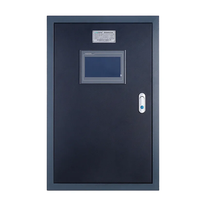
A LINECOME industrial automation PLC cabinet is a relevant starting point for a project discussion, but the required input modules, isolation, cable schedule and noise performance must be specified for the actual application. Product photographs show cabinet construction, not proof of a particular channel design or measured interference immunity.
Add filtering only with a response requirement
Filtering may be useful after the physical path and channel arrangement have been checked. First define how quickly a real process change must be recognized. Include alarms, interlocks, control loops and the operator display; they may need different response characteristics. A filter chosen solely because the screen looks calmer can delay action on a real change.
Keep the original setting and record each approved adjustment. Compare raw and processed values through both a steady operating period and a controlled process change. Test the alarm or control behavior that uses the filtered signal. Avoid adding several overlapping filters without identifying their combined delay and which system owns the accepted configuration.
Do not alter a safety-related measurement or trip path as part of ordinary display cleanup. Establish its design requirements and change controls separately. HSE’s control systems guidance discusses the different roles of process control, alarms and protective systems in major-hazard applications. The cabinet team should identify those roles explicitly instead of assuming every analog tag is interchangeable.
Plan the acceptance run and handover
Define acceptance before making changes: the operating modes to observe, the instrument reference to use, the allowed measurement variation and the required response time. These criteria belong to the process and equipment specification; there is no universal acceptable fluctuation for every pressure, temperature or level channel.
Run the conditions associated with the original complaint and record what changed. Include starts and stops of nearby equipment if they are suspected contributors and can be tested safely. Test more than one input level where possible, because one stable midpoint does not establish the channel’s full usable range. Record configuration, instrument identity, calibration status and the limits of the test.
Use the PLC cabinet FAT checklist to organize evidence and update the PLC program backup package when approved settings or application code change. Preserve the previous version, final drawings, cable route photographs and signed acceptance criteria. A useful closeout tells the next technician exactly what was tested, not simply that the reading looked better.
For an RFQ or service request, send the field device type, input module identification, signal range, cable length and construction, routing photographs, supply arrangement and paired raw/display trends. State whether the disturbance happens at idle, during switching or only under production load. That package helps distinguish an installation correction from a channel redesign and avoids ordering replacement hardware without an evidenced reason.
Further learning: analog input and output signals
RealPars explains analog signals and their role in PLC systems in the following educational video. Use it to clarify signal types before reviewing the channel drawing; it is not a wiring authorization or a noise acceptance test.
Video by RealPars. Watch Analog Inputs and Outputs in PLC Systems on YouTube.
Frequently asked questions
Should I increase the PLC analog input filter first?
First compare the raw value, displayed value and process indication. Filtering can reduce visible variation while adding delay, so agree on the required response and investigate the signal path before changing it.
Does a shield have to be connected at one end only?
There is no universal termination rule for every analog circuit. Follow the receiver and transmitter instructions and the approved bonding design, accounting for references and the interference environment. Never remove protective earth to improve a signal.
Does a stable reference signal prove the field sensor is faulty?
No. It validates the receiving path only at the tested boundary and operating condition. The remaining field cable, transmitter, supply and process still need to be separated through documented checks.


