




A PLC control cabinet FAT checklist should prove that the delivered cabinet matches its drawings and performs the agreed control functions before shipment. Start with documents and safe inspection, then test power supplies, every agreed input and output, operating modes, interlocks, alarms, communications and recovery behaviour. Finish with a controlled software backup and a signed list of exceptions. Factory acceptance testing reduces avoidable site problems, but it cannot prove field wiring or a process that is not present in the workshop. Define those boundaries before the witness test begins.
Agree the test scope before the cabinet arrives
A factory acceptance test, or FAT, is a contractual demonstration against an agreed specification. It is not simply a power-on inspection. Ask the owner, panel builder and controls engineer to agree which functions will be demonstrated, who supplies the simulators, and what constitutes a failed test. Name the drawing and software revisions used for acceptance.
Separate cabinet construction, application software and site integration in the test schedule. For example, the factory can simulate a tank-level input and demonstrate the resulting command, while the site’s actual instrument installation remains a site acceptance task. This distinction makes the final signature useful: the owner knows what was witnessed and what still needs verification after installation.
Establish entry conditions and a document baseline
Before energization, gather the electrical schematic, terminal schedule, bill of materials, cabinet layout, input/output list, control narrative and network architecture. Confirm that they describe the cabinet being tested. Check the device names used in the software against the names on the drawings and door labels. Resolve inconsistent identifiers before collecting test results.
The Denver Water-hosted project appendices provide an example of an owner specifying end-to-end I/O testing and witnessed acceptance. They illustrate the value of a defined scope, not a universal checklist for every industry. Adapt the project procedure to the actual cabinet, contractual requirements and site risks rather than copying an unrelated specification unchanged.
Inspect the cabinet in a de-energized state
Compare installed components with the approved bill of materials. Inspect terminal markings, protective-earth connections, cable entries, separation required by the design, ventilation provisions and access to replaceable parts. Confirm that door-mounted equipment and internal wiring can move through the intended door travel without strain. Record missing labels and unapproved substitutions as specific defects.
Electrical construction tests must follow the applicable assembly standard and manufacturer instructions. Sensitive electronics may require special treatment or disconnection for certain tests. Do not improvise an insulation or withstand test across connected PLC modules. Have competent personnel define the method, test equipment and acceptance criteria, then retain the measurements with the cabinet record.
Use a checklist that produces evidence
| Test group | What to demonstrate | Record to retain |
|---|---|---|
| Documents | Cabinet, drawings and software describe the same build | Revision list and exceptions |
| Power | Each designed supply and distribution branch behaves correctly | Approved measurements and equipment identifiers |
| I/O | Each included terminal maps to the right software point | Point-by-point results |
| Sequence | Permissives, modes and commands follow the narrative | Scenario sheets and observations |
| Alarms | Correct indication, priority, acknowledgement and recovery | Alarm test log |
| Communications | Data quality and loss-of-link response are defined | Network settings and failure-test results |
| Handover | A usable, controlled backup matches the tested version | Backup inventory and restoration instructions |
The table describes recommended evidence categories. Electrical limits, signal tolerances and response times must be filled in from the approved project documents. A blank acceptance value should be resolved before the test, rather than replaced by the observer’s impression that the result looks reasonable.
Energize in a controlled sequence
Use an authorized test arrangement with the intended protective measures, supply conditions and emergency arrangements. Follow the builder’s agreed energization procedure. Confirm each supply branch and device state in the planned order, checking for an unexpected indication before continuing. Keep loads that could move equipment disconnected or otherwise safely controlled until their test stage is authorized.
For servicing and wiring changes, use the site’s energy-control procedure. NIOSH explains that hazardous energy includes more than electricity; motion and stored energy can also create hazards. A software stop is not permission to reach into equipment. Distinguish planned energized functional testing from de-energized corrective work, with clear responsibility for changing between those conditions.
Check digital inputs from the terminal to the screen
For each included input, apply the approved simulated field state at the designated terminal. Confirm the correct PLC address, tag description, screen indication and control consequence. Test both states where relevant. A changed status bit inside the program proves less than a terminal-level test because it can bypass physical wiring and input hardware.
Record active-high or active-low behaviour and any filtering or delay expected by the narrative. For fault contacts, test the healthy and fault conditions, not just an arbitrary change of state. Check that a broken connection produces the intended indication where the design supports that diagnosis. Identify spare points separately so they are not accidentally accepted as active plant signals.
Verify analog values and engineering units
Use a suitable signal source and the approved injection points. Select test values that expose scaling errors, including intermediate values as well as the range endpoints where applicable. Compare the injected signal with the PLC value, HMI display and any resulting threshold action. Record units and allowed tolerance from the project specification.
A plausible number can still be wrong if it has the wrong scale, units or sign. Check how the system identifies an invalid or unavailable signal. Where the design uses signal quality or stale-data detection, demonstrate its consequence. Do not invent a universal out-of-range threshold: the sensor, input module and application requirements determine the appropriate settings.
Test outputs without creating unexpected movement
Agree whether outputs will operate real loads, indicator lamps or test devices. Trace each command through the intended terminal and feedback path. Confirm the output address and label, and check that a command to one device does not energize another. A software graphic changing colour is not evidence that the correct terminal changed state.
For analog outputs, verify the commanded range and the receiving-device assumptions. For motor commands, test the expected relationship between run demand and running feedback using safe simulation. Record delays only against defined requirements. If a field device is absent, clearly identify which part of the output chain was actually tested and which part remains for site acceptance.
Challenge permissives, interlocks and mode changes
Choose scenarios from the control narrative rather than testing buttons in isolation. Attempt a start with a missing permissive, remove a running permissive through an approved simulation, and check the resulting stop or inhibit. Confirm what must happen before a restart is allowed. Test local, remote, manual and automatic modes only as defined for the project.
A general PLC sequence test does not certify a safety function. Where safety-related controls are included, their design and validation require the applicable specialist procedure and competent review. Record that validation separately. Do not assume that an emergency-stop image on an HMI establishes a complete emergency-stop function or that ordinary application logic provides a required safety integrity level.
Include loss, recovery and operator understanding
Test the agreed response to a communications failure, unavailable remote data and a controlled power interruption. Verify whether commands are cleared or retained, how alarms appear, and what permits recovery. Unexpected automatic restart can matter more than the first successful start. The expected behaviour must be agreed before the test begins.
Ask the operator to explain what the displayed state means. Distinguish “commanded,” “running,” “available,” “faulted” and “communication unavailable.” Check that alarm acknowledgement does not silently reset a protective trip unless the approved design says it should. Screen wording and device identifiers should help the site team find the right equipment without guessing from a colour alone.
Control software and close the punch list
Save the tested PLC application, HMI application, hardware configuration and relevant parameter files. List software versions, licences or tools needed to access them. Agree a secure method for handing over authorized access details. Where restoration is in scope, demonstrate it on an appropriate test arrangement; merely copying a file is not proof that it can restore the system.
Classify unresolved items by their effect on shipment, safety and site work. Give each item an owner, due date and retest requirement. When a correction changes shared logic, repeat the affected scenarios as well as the failed test. Sign a final revision list so the delivered backup, drawings and cabinet all refer to the accepted build.
Connect the test plan to the supplied cabinet
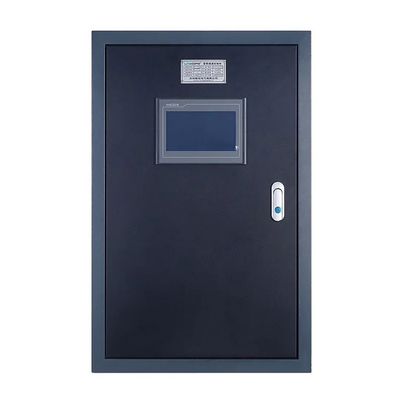
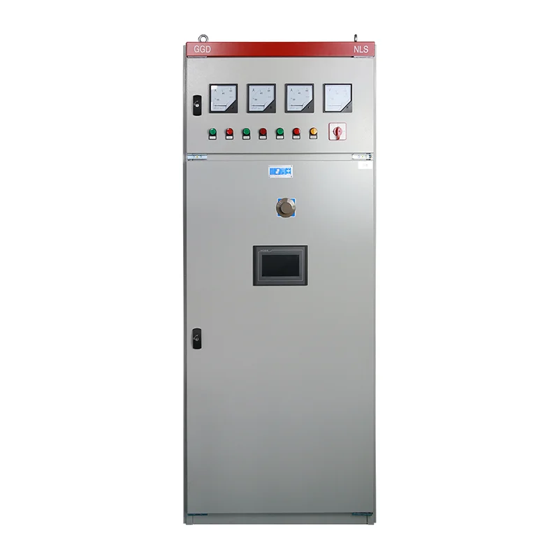
The LINECOME industrial PLC control cabinet is a relevant starting point for a project-specific enquiry. Ask for a scope covering the required signals, control functions, network interfaces and documentation. Product photographs illustrate cabinet configurations; they do not establish the PLC brand, installed I/O count or software scope of your order.
Use the site’s PLC cabinet overview for component-level context. The related installation and pump-control articles can help identify the separate field and process tests that should follow factory acceptance. Keep those links as supporting guidance; the signed test procedure must reference the actual order and approved control narrative.
Educational video: the first FAT stage
Video: RealPars. Watch Factory Acceptance Test Explained – Part 1 | Power the Control Panel on YouTube.
RealPars introduces powering a control panel as one stage of factory acceptance. The lesson helps explain the sequence to a mixed project team. Follow the authorized project procedure for actual testing; the video does not replace cabinet-specific inspection, electrical testing or safety validation.
Related LINECOME guides
- What Is a PLC Cabinet? Industrial Definition and Components
- VFD Installation — Field Wiring, Grounding, and Commissioning Checklist
- VFD Hoist Commissioning Checklist: Brake, Load and Acceptance Tests
Frequently asked questions
Is a successful power-on enough to accept a PLC cabinet?
No. Power-on confirms only part of the build. Acceptance should also cover the agreed I/O paths, control scenarios, abnormal conditions, documentation and tested software version.
Can factory testing replace site acceptance?
No. Field wiring, actual instruments, mechanical equipment and process conditions introduce interfaces that may not exist at the factory. List those site tests explicitly in the handover.
What should happen after a software correction during FAT?
Record the change and new revision, repeat the failed test and assess which other scenarios share the changed logic. Update the controlled backup and final documents before signing acceptance.


