




PLC sinking and sourcing inputs must match the sensor output and the common connection of the exact input group. In conventional DC terminology, a PNP sensor supplies current to a sinking input; an NPN sensor draws current from a sourcing input. Before ordering a replacement sensor or changing a cabinet, trace the complete current loop on the manufacturer’s diagram. A shared “24 V DC” label does not establish compatibility. Check the module part number, group common, electrical thresholds and intended logical state together. This guide focuses on ordinary discrete inputs, with a practical review and acceptance process for industrial PLC cabinets.
Identify the two devices before interpreting the label
Start with two separate records: what the field sensor does electrically, and what the PLC channel needs electrically. A supplier may describe an input by the sensor it accepts, whereas another describes current direction at the module. A catalog phrase such as “PNP compatible” is useful, but the connection diagram is the deciding evidence.
For background, the RealPars lesson on discrete sensor wiring explains complementary current paths. Use that concept to read the actual circuit, rather than assuming that a familiar label always implies the same terminal arrangement. This distinction becomes especially valuable when replacing an older module with a newer series.
Capture the sensor’s full ordering code, not just its family. Two visually identical proximity sensors may have different outputs. Capture the PLC module code and revision too. A cabinet exterior, screen or processor model cannot identify the installed input channel. Our PLC cabinet overview provides the wider system context; this article addresses the field-device interface within that system.
Draw the active current path and identify its return
For a conventional PNP arrangement, the active path runs from the positive supply through the sensor output, into the PLC input and back through the input common to the negative supply. For an NPN arrangement, current passes through the sourcing input circuit and then through the active sensor output to the negative supply. These are conceptual paths, not universal terminal instructions.
Mark each connection on the approved module diagram. Include the sensor supply and return, the switched signal, the module common and the relevant branch protection. If different supplies are involved, establish whether their references may be connected under the equipment instructions. Do not add a common or earth link simply because the signal currently appears unstable.
A normally open or normally closed function describes the response to detection. It does not define whether the transistor output is PNP or NPN. Record both characteristics in the device list. A replacement can be electrically compatible yet invert the intended machine indication, which is why the logic review must remain separate from the wiring review.
Review common groups before mixing sensor types
A PLC input group may share one common across several channels. Changing that common can affect every connected device in the group. Some modules accept either current direction, but that flexibility does not automatically mean different polarities can be mixed within a shared group. Other modules have individually isolated channels or different grouping arrangements. Only the specific manual resolves the permitted configuration.
The following review table is a qualitative planning aid based on the complementary circuits above and the RealPars discrete sensor wiring explanation. It does not replace a manufacturer terminal diagram or authorize a field modification.
| Evidence to collect | What it resolves | Action before approval |
|---|---|---|
| Sensor full code and output diagram | PNP, NPN or another output circuit | Match the actual output stage to the selected channel |
| Input module code and common diagram | Current path and channel grouping | Identify every channel affected by a common connection |
| Supply and reference arrangement | Whether the current loop is complete | Confirm allowed interconnections and isolation boundaries |
| Input and sensor electrical data | ON/OFF compatibility under load | Compare specified thresholds, leakage and output capability |
| Detection and PLC truth table | Expected normal and actuated states | Test the physical indication and program bit together |
| Replacement and spare-parts list | Future substitution risk | Record acceptable variants and prohibited substitutions |
If a proposed retrofit introduces a different sensor polarity, evaluate a compatible input group or a properly specified interface. An interface adds its own supply, response time, failure behavior and documentation requirements. Treat it as an engineered change rather than a convenient way to make one indicator turn on.
Check more than nominal voltage
A sensor can have the correct polarity and still fail to produce a reliable input. Compare the permitted supply range, output current capability, residual voltage in the active state and leakage in the inactive state with the PLC input specifications. Also check the input delay against the shortest valid event. Use actual datasheet limits rather than assuming a nominal control voltage guarantees adequate margin.
Two-wire electronic sensors need particular attention because their operating current shares the signal path. Relay contacts, three-wire transistor outputs and electronic two-wire devices should not be treated as interchangeable. A relay contact has no PNP or NPN transistor output, but its supply arrangement still has to suit the input circuit.
Review the installed circuit under realistic load. If several sensors lose their indication together, investigate shared wiring and supply conditions before replacing each device. The separate guide to PLC 24 V DC voltage drop addresses supply delivery and return-path measurements. It complements the compatibility check without changing the distinction between a voltage problem and an incorrect input type.
Diagnose the indication in four stages
First, confirm that the physical target is detected. Record the sensor indicator state and the mechanical condition that caused it. An indicator proves only what the sensor’s own documentation says it proves; it does not establish that adequate current reaches the PLC.
Second, examine the signal at the documented PLC terminals with the correct reference. A reading relative to protective earth can be misleading in a circuit whose reference is elsewhere. Measurements should be performed by competent personnel using a planned method appropriate to the cabinet hazards. Do not disconnect commons or move wires in an energized cabinet to test a theory.
Third, compare the channel indicator and the controller’s raw input value. If the module recognizes the event but the application does not, verify addressing, mapping, inversion, filtering and program conditions. Replacing the sensor will not correct a wrong input address. Preserve evidence of both the hardware channel and the software tag to avoid confusing two different faults.
Fourth, compare the application indication with the expected machine state. An HMI label may be inverted or represent a derived status rather than the raw input. Document the entire chain: physical condition, sensor output, channel bit and operator message. That chain makes the result reproducible for the next maintenance technician.
Plan a safe acceptance test
Prepare a point-by-point test sheet before commissioning. Identify the normal condition, the actuated condition and the expected input value for each. Include the approved response to a disconnected field device where testing is appropriate. A disconnected wire is not always distinguishable from a valid inactive state on a basic digital input.
Separate ordinary process indications from safety functions. Choosing PNP or NPN does not by itself create a safety-rated input, detect every wiring fault or establish a required safety performance level. Safety functions require the specified architecture, components and validation. Do not bypass a protective function to prove an ordinary input channel.
The HSE guidance on equipment maintenance emphasizes competent work, isolation and control of unexpected movement. Apply a site-specific method before opening the cabinet or manipulating a sensor that could command machinery. A software stop or forced input is not a substitute for the required safe condition.
Record failures that a simple lamp test can miss
Test the input across the intended operating sequence, not just with a stationary target. A sensor may switch correctly while stopped but produce pulses too short for the configured filter at production speed. Conversely, reducing the filter to capture a short event may admit unwanted changes. Establish the actual timing requirement before adjusting software settings.
Check the result after an authorized power cycle. Confirm that input configuration, addressing and the operator indication return as documented. Remove temporary forces and test links using the agreed restoration process. Record unresolved intermittent behavior rather than accepting a single successful cycle as proof of reliability.
For maintenance handover, preserve the final circuit drawing, part numbers, input-group assignments and test results together. Photograph labels only when access is safe. Record the test condition and instrument reference alongside any measurements. That information helps distinguish a later sensor failure from a changed configuration or an undocumented replacement.
Specify the PLC cabinet interface clearly
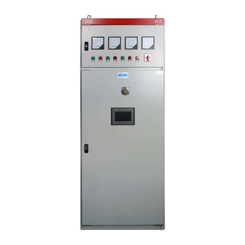
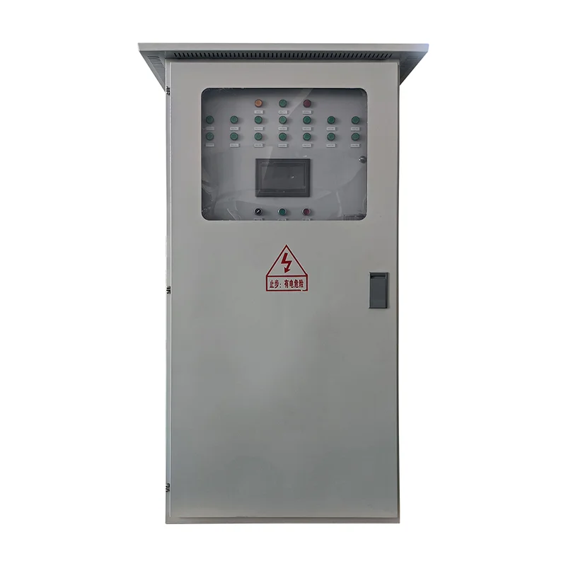
For a PLC control cabinet, provide an I/O list that names the sensor type, output circuit, supply requirements, channel grouping and normal state. Include device datasheets and any existing field-wiring constraints. The product photographs show cabinet construction examples; they do not establish the input hardware supplied for a particular order.
Ask the cabinet supplier to return a marked interface schedule and the exact input-module documentation. Require unresolved compatibility questions to be closed before wiring release. A useful response identifies the channel and diagram revision, rather than merely confirming “24 V inputs available.” Agree who supplies sensors, interfaces, cables and configuration files.
Use the PLC cabinet FAT checklist to integrate this point test into the broader acceptance plan. Keep the compatibility record as an attachment so future replacements can be assessed without reverse-engineering the whole machine. A clear spare-parts description should include output polarity and logical function, not just sensing distance or housing size.
Watch the discrete sensor current-path explanation
The following RealPars lesson explains three-wire DC sensor connections. Use it to understand complementary input and output roles; the installed device manuals remain the authority for terminal identification and electrical limits.
Video by RealPars. Watch How to Wire Discrete DC Sensors to PLC – Part 2 on YouTube.
Frequently asked questions
Does a PNP sensor need a sinking PLC input?
In conventional DC current-direction terminology, yes: the PNP output supplies current and the receiving input provides the return path. Confirm the actual wiring diagram because catalog labels may describe the compatible sensor instead of the module’s own current direction.
Can PNP and NPN sensors share one input module?
Only when the exact module and common-group arrangement explicitly permit the proposed combination. Separate isolated groups may offer options that a shared common does not. Check the documented circuit for every affected channel before changing the common connection.
Why is the sensor light on but the PLC input off?
Possible causes include an incompatible output type, an incomplete reference path, insufficient electrical margin, a wiring defect or an incorrect channel assignment. Trace the physical detection, terminal signal, raw input bit and application indication separately to locate the failed stage.


