




A VFD skip frequency setting prevents normal steady operation in a selected speed or output-frequency band associated with an unacceptable vibration response. Establish that band from the machine manufacturer’s guidance and measured behavior before changing parameters. The drive may still pass through the excluded region while accelerating or decelerating, so a successful setting requires both mechanical review and controlled functional tests. This guide explains how to define the evidence, distinguish mechanical speed from electrical frequency, and check that fan or pump control still works. It does not provide universal skip values or assert that every LINECOME drive implements the same function.
Establish whether the vibration follows speed
Record when the symptom occurs. A vibration that appears in a narrow operating region and diminishes outside it warrants investigation of a possible resonance. A symptom that continues across most of the speed range may require a different diagnosis. Neither pattern alone identifies the fault, and an audible change is not a substitute for a mechanical assessment.
Keep a record of speed, operating load and vibration at repeatable measurement locations. Include the driven machine and supporting structure, rather than looking only at the motor. Belt drives, couplings, fan assemblies, pipework and foundations can introduce relevant responses. Have a competent machinery specialist define the measurement method and acceptable limits for that installation.
The U.S. Department of Energy fan sourcebook identifies resonant speeds as a concern when varying fan speed and calls for input from both fan and drive manufacturers. This is a reason to investigate the complete assembly. It does not identify a safe speed band for any particular fan or establish that a new setting will repair a mechanical defect.
Keep three different frequencies separate
The drive’s motor output frequency, the shaft rotational frequency and the PWM carrier frequency are different quantities. A speed exclusion normally concerns where the machine operates, whereas carrier frequency concerns the inverter’s switching behavior. Changing a PWM setting because the machinery shakes can address the wrong mechanism and introduce additional thermal or acoustic effects.
For a simple illustration, shaft rotational frequency in hertz equals measured rotational speed in revolutions per minute divided by 60. A measured 1,200 rpm is therefore 20 revolutions per second. This arithmetic does not make 20 Hz the correct drive setting: motor pole count, slip, gearing and the displayed parameter units still matter. Use measured speed and the actual drive documentation to establish the relationship.
A vibration component can also occur at a multiple of shaft speed. Record which shaft and measurement point the observation refers to. Do not enter an analyzer’s peak frequency directly into a drive parameter without establishing its meaning. The underlying forced-response concept is explained in MIT’s lecture on driven oscillators and resonance.
Inspect the machine before creating an exclusion
Review obvious mechanical changes and maintenance history. Loose fasteners, altered supports, deposits, damaged components, alignment problems or a replacement impeller can change the vibration response. A skip band can restrict operation, but it does not correct those conditions. Where inspection is needed, stop and isolate the equipment under the approved method before accessing it.
Ask whether the machine had previously operated acceptably at the same speed. A newly developing symptom at an established operating point deserves a fresh condition assessment. Expanding a band repeatedly can hide deterioration and progressively remove useful operating range. Record why the change is being proposed and what evidence rules out an immediate mechanical repair requirement.
Separate the acceptance question from the production-pressure question. “The noise disappears above this speed” is an observation. “The machine can safely cross this region and operate elsewhere for its required duty” is a conclusion requiring evidence. A control setting should not be used to bypass a machine manufacturer’s prohibited operating condition.
Build a usable speed-band record
Prepare a record before the controlled test. Identify the installed motor, drive, transmission, driven load and drawing revision. Include load conditions because a no-load workshop result may not represent the installed process. The following table is an engineering review framework, not a table of universal vibration limits or parameter values.
| Record | Why it matters | Evidence required for acceptance |
|---|---|---|
| Actual shaft speed and drive display units | Prevents entering the wrong quantity | Confirmed relation between displayed value and measured machine speed |
| Vibration location and measurement method | Makes comparisons reproducible | Marked locations, instrument details and recorded operating state |
| Suspect region and adjacent operation | Defines the observed response | Results below, within and above the region under a safe test plan |
| Required process duty | Reveals whether an exclusion is usable | Normal demand points remain achievable outside the restricted region |
| Acceleration and deceleration behavior | Checks passage through the region | Approved transition response without unacceptable vibration or process upset |
| Control mode and command source | Identifies paths that may behave differently | Verified operation from each authorized command path |
| Parameter revision and approval | Supports restoration and later maintenance | Baseline backup, final values and named acceptance responsibility |
Use limits established for the actual machine and measurement conditions. An overall vibration reading without its units, location, bandwidth and operating state cannot support a reliable comparison. Avoid copying a limit from unrelated machinery or treating one acceptable reading as proof for every duty point.
Confirm the exact drive function
Obtain the installed drive manual and software revision. Manufacturers can define an exclusion using lower and upper boundaries, a center and bandwidth, or another arrangement. Units, number of available bands and behavior at a band edge can differ. The parameter name alone does not resolve these details.
Ask how the function behaves with local control, remote references, presets, PID control and communication commands. Also establish whether it applies to acceleration, deceleration, steady references or selected modes only. These are questions for the specific drive documentation and functional test; they are not assumptions to carry from a different brand’s guide.
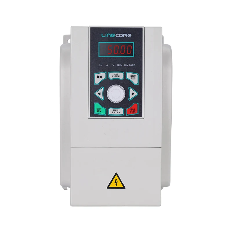
The LNC860S vector VFD product page provides a starting point for discussing the drive family. Its photograph is not evidence of a skip-frequency parameter, firmware capability or suitable setting for a particular machine. Require written confirmation of the ordered configuration and the relevant manual before including the function in a purchase specification.
Test the excluded region without creating a new problem
Define the test limits, stop criteria and responsibilities before energizing machinery. Controlled speed exploration must respect the machine manufacturer’s limits and the site’s safeguarding arrangements. Stop if the response exceeds the approved criteria; do not continue searching for a quiet speed through potentially damaging behavior.
Check both increasing and decreasing demand after a proposed exclusion is implemented. Document the drive output and actual process response. The drive may handle a command inside the restricted region by using a boundary or another defined behavior. The test must show what this implementation actually does, not what the engineer expects from a familiar parameter name.
Acceleration and deceleration need separate attention. Passing through a band more quickly may require additional torque or change process transients. Passing more slowly may expose the assembly to an unacceptable response. Use the VFD acceleration and deceleration guide for the broader ramp review, then validate the chosen behavior with the machinery and process specialists.
Check PID control and operating coverage
For a fan or pump under closed-loop control, review the operating points near each band boundary. A demand that falls inside a restricted region may lead to an unavailable steady operating point. Check whether the process can meet its requirements at the permitted alternatives, and observe how the controller responds as demand changes through that region.
Do not solve an unstable process response by widening the speed band without understanding the interaction. Log the setpoint, measured process value, command and actual speed together. That record helps distinguish a mechanical restriction from a tuning, sensor or process-capacity issue. An exclusion that eliminates a vibration complaint but prevents required duty is not a complete solution.
Include startup, shutdown and any authorized manual operating modes in the acceptance sequence. Where multiple machines operate together, review the relevant combinations. A test on one fan alone may not represent operation with adjacent equipment, altered duct conditions or a different support loading. Record which combinations were actually tested and which remain outside the approval.
Preserve the result for maintenance
Keep the original parameter backup and the approved final version. Record the observed speed region, the rationale for its boundaries, the applicable duty and any unresolved limits. Include the mechanical inspection findings, not just a screenshot of the parameter page. This provides a basis for deciding whether a future change is a restoration or a new engineering modification.
The HSE equipment maintenance guidance supports planned maintenance and competent intervention. For this task, apply that discipline by assigning an owner to later vibration changes. If the suspect region shifts or broadens, investigate the machine condition rather than assuming the previous approval covers it.
For general drive behavior, see how a variable frequency drive works. For switching noise and thermal tradeoffs, the separate carrier frequency guide explains a different parameter family. Keeping these records separate prevents a technician from restoring the wrong setting during a future troubleshooting visit.
Watch the resonance principle
MIT OpenCourseWare’s lecture below explains driven oscillators, transient response and resonance. It provides physical background for understanding why a narrow operating region can produce a large response. It is not a drive setup tutorial or authorization to test machinery beyond its approved limits.

Video by MIT OpenCourseWare. Watch 3. Driven Oscillators, Transient Phenomena, Resonance on YouTube.
Frequently asked questions
Is skip frequency the same as carrier frequency?
No. A speed or output-frequency exclusion concerns the operating region of the driven machine. Carrier frequency concerns inverter switching. Confirm parameter units and the suspected vibration mechanism before changing either setting.
Does a skip band prevent the motor from crossing resonance?
Not necessarily. Many implementations restrict steady operation while still passing through the region during a ramp. Confirm the exact function and validate transition behavior against the machine manufacturer’s requirements and measured response.
Can the same skip values be copied to an identical machine?
Treat another installation’s values as background information only. Mounting, transmission, process duty and machine condition can change the response. Verify the installed assembly, parameter meaning and operating requirements before approving its own settings.


