




A VFD hoist commissioning checklist should prove that the drive, motor, mechanical brake and protective devices work together throughout a complete lifting cycle. A motor that rotates correctly with no load has passed only an initial check. Before releasing a retrofitted hoist for production, the responsible team must verify controlled pickup, loaded lowering, brake transfer, travel limits, fault responses and the approved restart behavior. This guide explains what evidence to collect and how to organize acceptance; it does not supply universal brake timings or authorize changes to a hoist safety circuit.
Our guide to the benefits of a VFD on an electric motor hoist covers the reasons for adjustable lifting speed. This article addresses a different task: documenting whether an assembled system is ready for service. The test sequence and acceptance limits must come from the hoist manufacturer, approved engineering design and applicable local requirements.
Define the acceptance boundary before energizing
Start with the exact machine identity, rated capacity, operating environment and intended duty. Record whether the work is a like-for-like replacement, a control modernization or a change in operating capability. A new drive can alter acceleration, stopping distance and behavior after a supply interruption even when motor power stays unchanged. Those changes require review before a commissioning team experiments with settings.
Assign responsibility for electrical inspection, mechanical brake inspection, functional testing and final release. Put drawing revisions and parameter-file versions on the same acceptance record. If the mechanical contractor uses one brake drawing while the controls engineer uses another, successful individual component checks do not establish that the combined system is correct.
For US overhead and gantry cranes within its scope, OSHA 1910.179 provides requirements covering brakes, inspection and testing. Its holding-brake and control-braking provisions should be reviewed by the responsible engineer. Other crane types, jurisdictions and service conditions may have different rules; this checklist is not a declaration of compliance.
Collect the documents that make a result meaningful
The acceptance file needs motor nameplate data, the selected drive manual, approved power and control drawings, brake information and the manufacturer’s permitted operating envelope. Include encoder details where feedback is used, motor thermal sensor arrangements, gear ratio and the authorized hook-speed range. A photograph of a keypad cannot replace the complete parameter backup.
Identify every component that can interrupt motion: normal stop, emergency functions, upper and lower travel limits, overload devices, motor thermal protection and drive faults. For each one, document the expected sequence and the party approving the response. Keep ordinary operational controls distinct from safety functions; an available digital input does not establish a safety rating.
Also identify how auxiliaries are powered. A brake coil, panel transformer or cooling fan may need a separate supply with its own switching and protection. Do not assume it belongs on the drive’s motor output. The current drawing must show the actual arrangement and any interlocks that prevent unintended brake release.
Use a staged acceptance matrix
The following matrix is a planning aid. It intentionally avoids numerical limits because permissible drift, stopping distance, test loads and timing depend on the approved hoist design. Fill the acceptance column before testing, then attach measured observations rather than replacing evidence with a general “works correctly” note.
| Stage | Evidence to record | Acceptance basis |
|---|---|---|
| Installation review | Wiring revision, protection, earthing, motor and brake identification | Approved drawings and equipment manuals |
| Initial motion | Command direction, feedback direction and permitted travel | Approved controlled test procedure |
| Brake transfer | Release and application sequence, feedback and observed movement | Hoist manufacturer’s brake-control design |
| Loaded cycle | Pickup, lowering, low-speed response and stopping behavior | Authorized load-test plan and operating envelope |
| Protective response | Test method, response, resulting brake state and restart state | Approved cause-and-effect specification |
| Duty review | Temperatures, repeat-cycle behavior and braking-system observations | Component ratings and accepted duty profile |
Complete static inspections before motion tests
Qualified personnel should inspect mounting, cable support, protective earth connections, separation of power and feedback wiring, and environmental protection. Verify brake supply voltage against its actual nameplate. Check that terminal labels match the drawings and that the drive’s output-current capability is suitable for the motor and specified duty after relevant derating.
Electrical inspection requires an appropriate safe-work procedure. OSHA 1910.333 addresses electrical work practices, including stored energy and verification of deenergization. Follow the drive manufacturer’s discharge instructions; an extinguished display does not prove that the DC link is safe. Mechanical stored energy and suspended-load hazards also need controlled treatment.
Never make a checklist an excuse to bypass a protective circuit. Resolve inconsistent drawings, missing brake information or unexplained contactor arrangements before energizing. A drive fault can be a useful symptom of an installation error; repeatedly resetting it without establishing the cause can conceal an unresolved defect.
Verify direction and motor feedback under a controlled plan
Confirm that each operator command corresponds to the intended motion. When encoder feedback is fitted, its direction and scaling must agree with the motor-control setup. An incorrect feedback sign can produce an unstable response. Use only the manufacturer’s prescribed commissioning method with the machine in the approved safe condition.
Motor identification or autotuning procedures deserve particular attention. Some procedures rotate the shaft or require a specific mechanical condition. Do not run a rotating tune on a connected hoist simply because that option appears in the menu. Obtain the hoist and drive manufacturers’ accepted method and preserve the resulting motor data.
Record control location and command priority as well. Local keypad, pendant, remote controller and communications commands should have a documented ownership arrangement. Test the authorized transitions between them. Unexpected motion when control returns from local to remote is an acceptance issue even if every steady-state speed command is accurate.
Prove mechanical brake transfer without inventing timings
Brake transfer is the coordinated exchange between motor torque and mechanical holding action. The engineering design must determine the conditions for releasing the brake and for applying it during a normal stop. A generic delay copied from another hoist cannot establish correct transfer on a different brake, gear train or motor.
Observe commanded state, available feedback and actual movement together. A relay changing state proves a command was issued; it does not prove that a mechanical brake opened or closed. Where the design provides brake feedback, record its response and the specified behavior when that response is absent or inconsistent.
Keep drive braking and mechanical holding separate in the acceptance record. Electrical deceleration can manage moving-load energy, while the holding brake has its own duties. Do not treat a drive’s zero-speed command or torque-producing capability as permission to remove or bypass the specified mechanical holding system.
Check lowering energy and repeated operating duty
During lowering, a suspended load can return mechanical energy through the motor. The selected system must have an approved path for that energy, such as a properly engineered resistor system or a suitable regenerative arrangement. Confirm the installed components and ratings against the design rather than assuming an optional braking feature was included in the supplied model.
A single successful lowering movement does not prove repeated-duty capability. Observe the agreed operating cycle, including load, travel, dwell and starts per period. Record drive and motor thermal indications, braking-system condition and any warnings. Do not touch energized or hot components to estimate temperature.
Use our braking resistor sizing guide for the questions that belong in an energy review, and our acceleration and deceleration guide for ramp terminology. Neither replaces hoist-specific engineering. A longer ramp may reduce one electrical stress while creating an unacceptable travel or stopping result.
Test protective responses and restart conditions
The approved cause-and-effect document should state what happens after each relevant protective event. Check the intended brake state, torque removal sequence, operator indication and reset requirements. Simulate conditions only by an authorized method; do not create hazardous faults or defeat a limit device to see what happens.
Power loss and restoration deserve an explicit review. The team should establish whether a retained command can restart motion, whether an operator acknowledgement is required and how the system proves readiness. Record communications-loss behavior separately because loss of a network reference may differ from removal of mains power.
Where maintenance or inspection exposes people to unexpected movement, the energy-control procedure must address the real hazards. OSHA 1910.147 describes hazardous-energy control for covered servicing activities. A normal stop command is not an energy-isolating procedure. Apply the applicable electrical and mechanical safe-work requirements together.
Close the acceptance file and control later changes
Keep the final parameter backup, drawings, component list, test conditions, measured results, unresolved items and sign-off together. Record the actual load and duty used during testing. If production will use a different operating pattern, the test evidence must not be presented as validation of that untested condition.
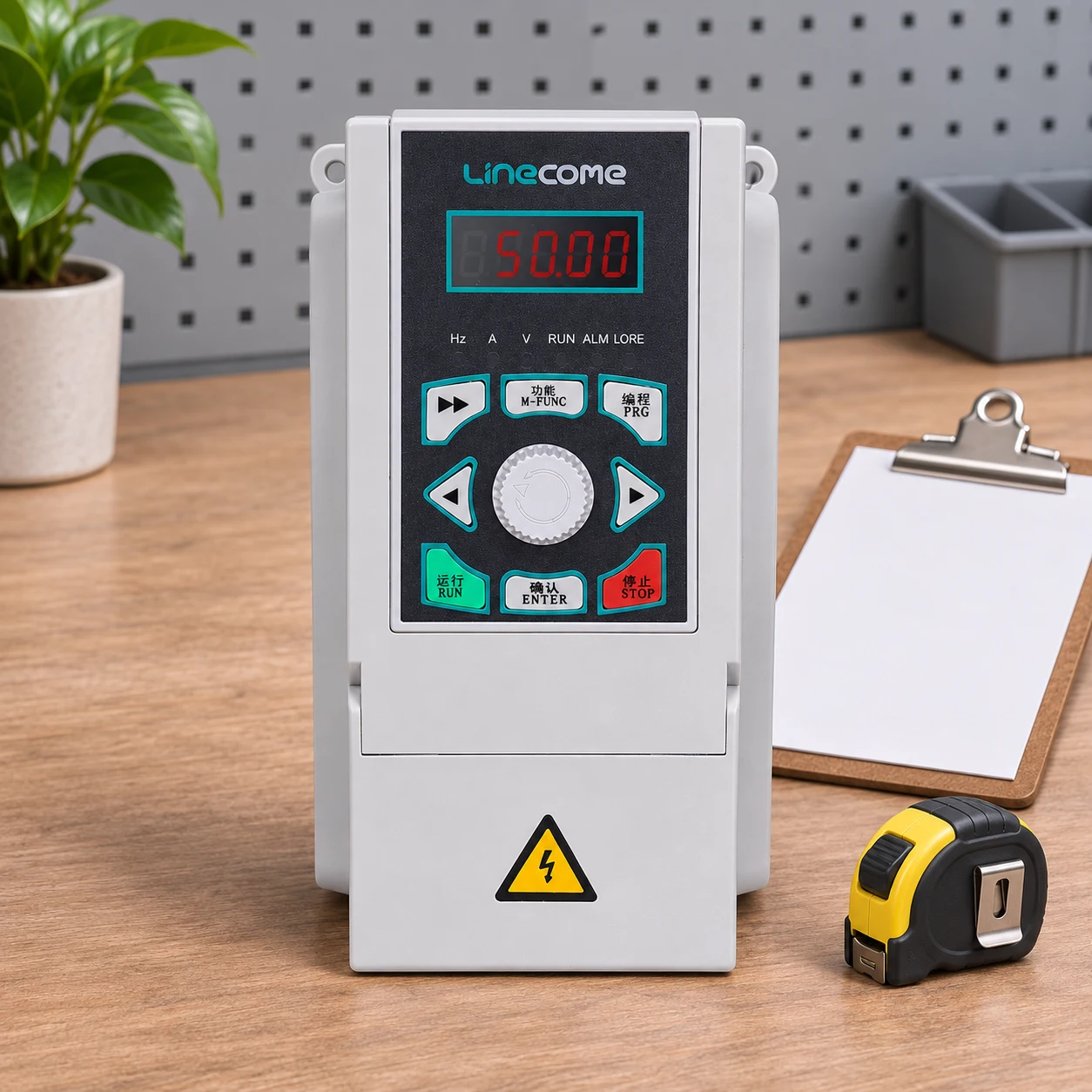
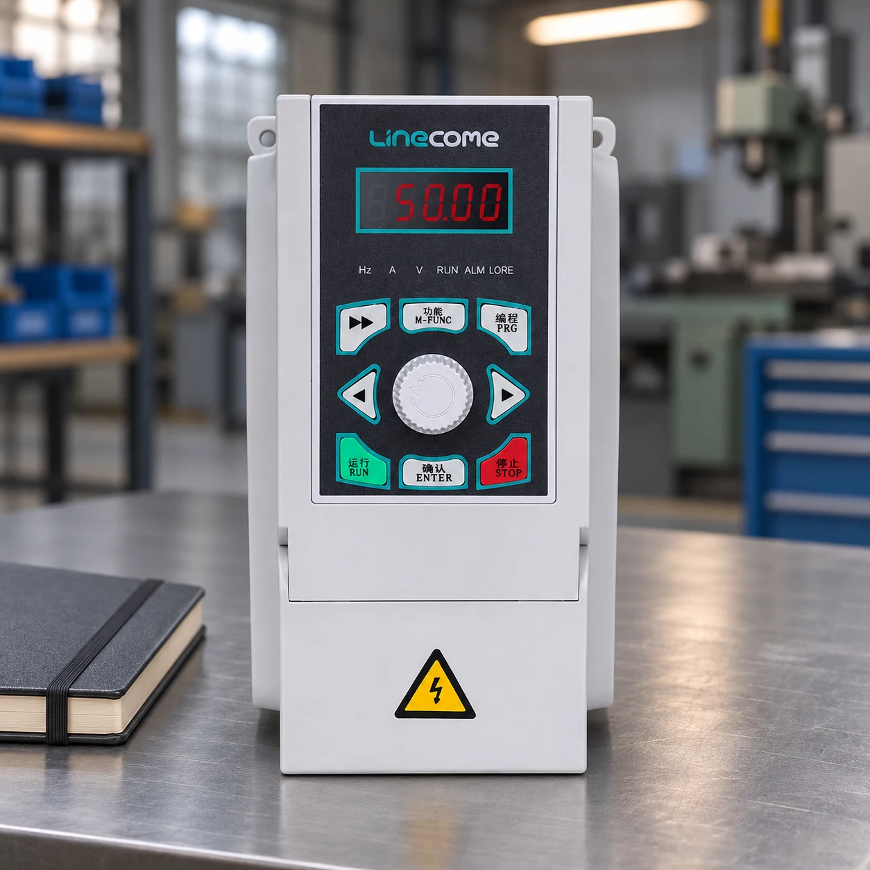
For a product discussion, provide LINECOME with the nameplate, supply details, braking arrangement, feedback requirements and approved duty specification. The LNC820 general-purpose VFD range illustrates motor-drive hardware, but a catalog listing or the product photograph in this article does not establish suitability for a particular hoist. Request written application confirmation for the exact model and control design.
After handover, manage parameter changes as controlled changes. Increasing maximum speed, reducing a ramp or altering brake logic can invalidate earlier acceptance evidence. Preserve the accepted version and require the responsible team to identify which tests must be repeated before the changed machine returns to service.
Further learning: the motor-drive power stage
The Engineering Mindset’s explanation below introduces the rectifier, DC link and inverter. It provides background for understanding drive behavior; it is not a hoist brake-setting or safety-validation procedure.
Frequently asked questions
Does a no-load run prove a VFD hoist is ready for service?
No. It is an initial motion check. Loaded behavior, brake transfer, protective functions, duty capability and the documented acceptance requirements still need verification.
Can the drive hold the load instead of the mechanical brake?
Do not substitute a drive command for the specified holding brake. The approved hoist design and applicable requirements determine the required holding and braking arrangements.
Should every hoist use the same brake release delay?
No. Brake response, motor control, feedback and mechanical characteristics differ. Use the approved manufacturer-specific sequence and verify the actual response.
What should be saved after commissioning?
Save the final drawings, parameter backup, component identities, test plan, measured results, outstanding-item closure and authorized release record.


