




A soft starter bypass contactor carries motor current after the starting ramp, reducing the time that current flows through the starter’s power semiconductors. Selection depends on what the contactor must actually switch, the motor current, the protection arrangement and the approved starter circuit. A normal run bypass and an emergency full-voltage starting path have different duties. Begin with the exact starter manual and an agreed operating sequence, then verify the complete assembly. This checklist helps buyers define that handoff without treating a catalogue current rating as a finished design.
First define what “bypass” means
In normal run bypass, the starter accelerates the motor before the bypass contactor closes. The controller coordinates the transfer and, where applicable, the return to semiconductor control for stopping. An emergency bypass may instead start the motor directly from the supply when the soft starter is unavailable. That introduces starting and switching duties that a run-only contactor may never experience.
Write the required behaviour into the quotation. Ask whether bypass operation is automatic, manually selected, or prohibited during a fault. State whether a failed starter must be isolated before another starting path can operate. Do not use the words “with bypass” as a substitute for a reviewed drawing and an explanation of the sequence.
Map the current path before choosing hardware
Mark the supply, protective device, starter, bypass contactor, current sensors, overload function and motor on one drawing. Follow the current path during acceleration, normal running, stopping and each intended fault response. The important question is whether the protection still measures the motor when the bypass is closed.
The JICA motor-starter training material illustrates soft starters within a wider motor-control system. It is useful background for separating the starter from the surrounding switching and protection equipment; it does not approve a particular LINECOME contactor combination. For the proposed assembly, require a model-specific circuit and a written description of which protective functions remain active in each operating state.
Selection questions to put in the RFQ
| Decision | Information to provide | Evidence to request |
|---|---|---|
| Motor load | Nameplate current, voltage, load type and starting conditions | Selected starter and contactor references |
| Switching duty | Run bypass only or direct starting capability | Manufacturer’s permitted duty and sequence |
| Control supply | Nominal voltage, supply source and expected variation | Coil specification and control-circuit drawing |
| Motor protection | Sensor positions and protection in every mode | Current-path diagram and overload settings |
| Fault withstand | Available fault current and upstream protection | Applicable assembly coordination documentation |
| Installation | Cabinet temperature, altitude and switching frequency | Derating review and maintenance access |
This is an engineering enquiry table, not a universal sizing chart. The exact permissible switching category and current rating must come from the component manufacturer and the approved circuit. A contactor that is suitable for one transfer arrangement should not be substituted into another arrangement solely because the motor power is the same.
Check current and switching duty separately
The motor nameplate establishes an essential operating-current reference, but current alone does not describe how a contactor will be used. Ask whether it closes after the starter has established the running condition, whether it can interrupt a loaded motor, and what occurs if a transfer command or feedback signal is lost.
Do not apply a general multiplier from an unrelated starter to the PR800 range. Supply voltage, enclosure conditions, switching requirements and the selected manufacturer’s instructions must all agree. Where the proposal includes emergency direct starting, also confirm that the supply and driven equipment can tolerate that event. A run-bypass design does not automatically provide a tested emergency starting facility.
Confirm overload sensing during bypass
A display showing a current value during acceleration does not prove that the same measurement remains valid after transfer. Have the builder identify the sensors on the drawing and describe their relationship to the bypass conductors. Ask which device initiates a motor overload trip during running, and how that trip opens the necessary power path.
The acceptance record should name the protective function, its settings and the approved test method. Simulate the relevant signal or use the manufacturer’s test facility where permitted. Do not deliberately overload the motor merely to demonstrate a trip. If an external overload device is required, its settings and wiring belong in the same document package as the starter settings.
Review short-circuit protection as an assembly
A breaker interrupting rating and a complete panel short-circuit current rating are different pieces of evidence. UL’s combination motor-controller guidance explains that combination ratings concern specified components and protective arrangements. Its North American framework should not be represented as certification of an unreviewed export panel.
For the project jurisdiction, ask the builder to identify the applicable method, protective-device reference and any conditions on conductor size or settings. Do not assume that adding a high-rated incoming breaker gives every downstream component the same rating. Keep the review tied to the actual bill of materials rather than a similar cabinet photographed in a catalogue.
Make the transfer sequence observable
The sequence should distinguish a run request, acceleration in progress, permission to close bypass, contactor feedback, normal running and stop. Record the conditions needed for each transition. A fixed delay may form part of an approved design, but it should not conceal the absence of the required starter status or contactor feedback.
During commissioning, compare the requested state with the observed contactor state and motor behaviour. If bypass fails to close, identify the designed response before attempting repeated starts. If feedback indicates a closed contactor while the command is absent, stop testing and investigate. Temporary links used during a factory test must be listed and removed before release.
Coordinate soft stopping with bypass operation
When a process needs soft stopping, the approved sequence must provide the required transition from bypass to starter control. Ask the supplier to explain the order of operations and how an abnormal transfer is handled. “Soft stop available” in a product description is not enough to establish that the assembled bypass circuit implements it correctly.
For pumps, agree the intended hydraulic outcome with the process engineer. A slower voltage reduction does not by itself establish an acceptable pressure transient. Where stopping behaviour matters, specify what will be observed at the site and which measurements will be retained. Factory electrical checks and site hydraulic acceptance answer different questions and should have separate sign-off records.
Inspect the physical assembly without changing the product
Check that the supplied starter and contactor references match the drawing. Inspect terminal identification, conductor routing, clearances specified by the manufacturers, protective-earth arrangements and access for maintenance. Use specified tightening procedures; avoid inventing a torque based on terminal appearance. Confirm that covers can be restored without disturbing conductors.
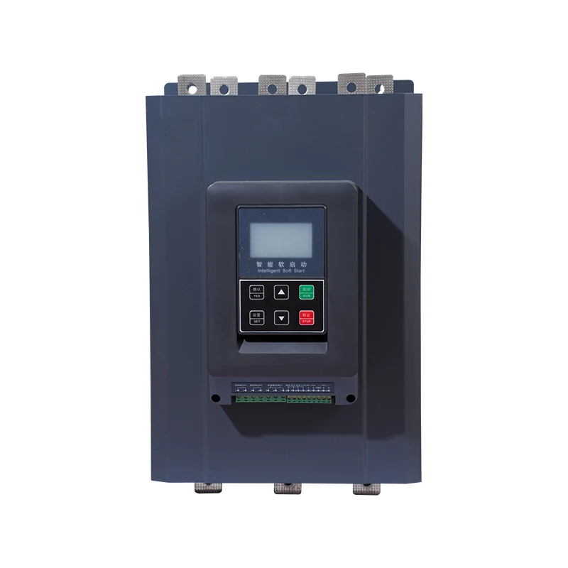
The photographs show original PR800 products from the website on plain backgrounds. They help identify the product family and visible construction, but do not establish a wiring configuration, protective rating or completed installation. Compare the actual delivered hardware and its documentation with the order. A cabinet builder’s approved drawing remains the reference for the assembled system.
Prove control behaviour before a loaded run
Begin with a documented, safe factory test plan. Confirm the control supply and permitted simulation points before applying signals. Verify the run and stop commands, starter status, contactor command, feedback and alarm indications. Include loss of a required permissive and a failed-transfer scenario where simulation is allowed.
Service work requires isolation and control of hazardous energy, including stored energy and remote starting commands. NIOSH hazardous-energy guidance provides the safety basis for preventing unexpected energization. Energized tests need a separate authorized procedure and competent personnel. Operating a selector switch or opening a software screen does not replace physical energy isolation for servicing.
Define a useful acceptance record
For each test, record the starting condition, command, expected response, actual response and evidence. Include the drawing revision, firmware or settings revision, tester and witness. If a test fails, write the cause and corrective action, then repeat the affected sequence. A final “runs normally” note is too vague to resolve a later protection or transfer dispute.
Keep the motor nameplate, starter settings, contactor data, protective-device details and final circuit together. List anything that could not be demonstrated at the factory, especially loaded starting, pressure behaviour or interaction with a site supply. Those items should become named site tests with responsible owners rather than disappearing into an unconditional factory acceptance signature.
Match the enquiry to the actual product family
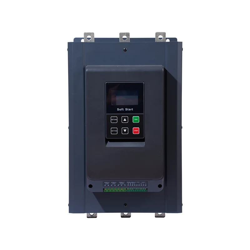
The PR800 external-bypass soft starter is the relevant LINECOME starting point for an external-bypass enquiry. Request the exact frame’s approved bypass circuit, control-output capability, protection coverage and duty assessment. The product page alone should not be used to infer a universal contactor size or unlimited starting frequency.
For the broader sequence, read how a soft starter works if that is the established topic in your document pack, and compare the site’s existing installation and repair guidance when preparing the handover. These explain different tasks: operating principles, physical installation and fault investigation. Keep the bypass selection record focused on switching and protection evidence.
Educational video: understand the starting stage
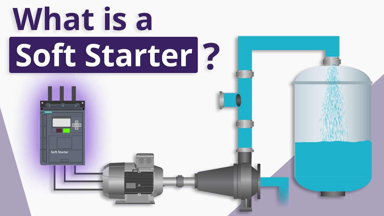
Video: RealPars. Watch What is a Soft Starter? (For Absolute Beginners) on YouTube.
RealPars explains the basic soft-starting principle in this educational introduction. It provides context for why a bypass stage can follow acceleration. It is not a wiring approval or a model-specific contactor selection guide; use the approved PR800 documentation for those decisions.
Related LINECOME guides
- How a Soft Starter Works — Ramp, Bypass, and Start/Stop Sequence
- How to Install a Soft Starter — Cabinet, Environment, and Install Acceptance
- Soft Starter Repair — Troubleshooting and Field Test Guide
Frequently asked questions
Can any contactor with the same current rating be substituted?
No. Switching duty, coil supply, environment, protective coordination and the manufacturer’s approved circuit must also match. Treat a proposed substitution as a drawing and bill-of-materials change requiring review.
Does bypass remove the need for overload protection?
No. The motor still requires the protection specified by the project. Confirm how motor current is sensed and which device trips during bypass operation instead of assuming the starter’s acceleration display proves running protection.
Can a run bypass start the motor directly in an emergency?
Only if the assembly has been designed and verified for that purpose. Direct starting changes the contactor duty and can affect the supply, motor and process. It must be explicitly included in the approved design.


