




Soft starter phase loss is a protection indication that requires tracing the supply, current path and operating state before resetting the equipment. The label alone does not prove that the utility has lost a phase or that the starter’s electronics are defective. Record whether the event occurs before a start command, during acceleration, at bypass transfer or during steady running. Then compare the exact manual’s detection conditions with evidence from the incoming circuit, motor connections and bypass path. Preserve the first fault record before repeated attempts erase the useful sequence.
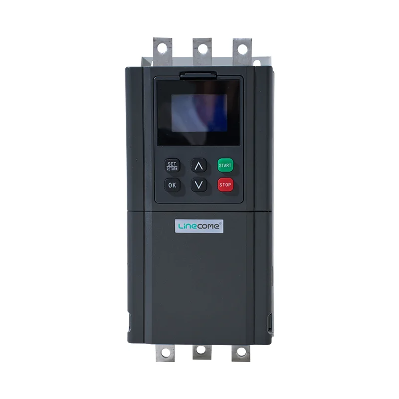
This guide concerns ordinary low-voltage squirrel-cage motor applications. It does not provide medium-voltage testing instructions or universal fault thresholds. The LINECOME NR1000 built-in-bypass soft starter is a relevant catalog family, but its photograph cannot identify a protection setting or establish the configuration supplied for a project. Start with how a soft starter sequences ramp and bypass if the operating states are unfamiliar.
Treat the trip message as a starting point
Different starter designs use different sensing arrangements and detection logic. A current-based missing-load indication is not identical to direct supply-voltage monitoring. Detection can depend on operating state, load and configuration. Read the exact model manual, including the conditions under which the protection is active, instead of applying another manufacturer’s threshold or reset sequence.
Keep related terms distinct. Phase sequence concerns the order of the phases. Voltage unbalance concerns unequal phase-to-phase voltages. A missing motor conductor concerns continuity downstream of the starter. These conditions can produce different symptoms even when an operator describes all of them as a phase problem. Ask for the actual displayed code, its full text and the time it appeared.
The Natural Resources Canada electric-motor reference guide distinguishes phase-failure protection from ordinary fusing and overload protection. That distinction explains why the complete protection arrangement must be reviewed when investigating a missing-phase event. Obtain product-specific procedures from the installed equipment documentation; a general reference does not authorize component replacement or protection-setting changes.
Preserve a timeline before changing anything
Record the last successful operation and the first failed attempt. Note recent motor replacement, fuse work, cable maintenance, control changes and supply disturbances. Save the starter event log, PLC sequence and any upstream protection record before cycling control power. A photograph of the final alarm alone may omit the event that actually initiated the stop.
Identify the operating state at the moment of failure. A trip immediately on command suggests different checks from one appearing after several minutes of running. A failure associated with bypass transfer requires the transfer sequence and current path to be examined. An intermittent event after maintenance makes the changed connections important, but does not establish that they are the cause.
Align timestamps where possible. If the PLC says the run command was removed before the starter fault, determine why that command disappeared. If the starter fault comes first and the PLC reacts afterward, the sequence points in another direction. Record uncertainty when clocks are not synchronized rather than inventing a precise order.
Establish safe isolation for physical inspection
Stop the process through the approved operating procedure, isolate all relevant energy sources and verify the condition with appropriate equipment. Include separate control supplies and auxiliary circuits. The official electrical work-practice text explains why a stop pushbutton or interlock is not a substitute for electrical isolation. Local requirements and the site’s qualified-person procedures govern the actual work.
Do not repeatedly start a motor that may have an open phase. Do not bridge protective devices, force contactors or disable phase monitoring to keep production moving. A reset removes an indication; it does not repair the conductor, supply or component that caused it. Establish the reason a further test is safe before authorizing another attempt.
For offline inspection, use the manufacturer’s terminal identification and approved tightening information. Look for damaged conductors, poorly seated connections, heat discoloration, fuse-holder damage and signs of contamination. Record findings before disturbing the assembly where practical. A connection that appears tight externally can still require a qualified assessment; appearance alone is not acceptance evidence.
Trace the incoming circuit before blaming the starter
Follow the approved single-line diagram from the supply through disconnects, fuses, circuit breakers and line contactors to the starter. Verify which devices actually carry motor current and which only switch a control supply. A healthy keypad display establishes that some control power exists; it does not prove that all three power phases are present under the relevant conditions.
Any necessary energized measurement must follow an approved qualified-person procedure. Compare all relevant phase-to-phase readings with the installation and motor requirements, and record the operating state. A reading taken with the motor stopped may fail to reveal a connection that deteriorates when current flows. Choose instruments and a measurement method suitable for the circuit and waveform.
If the incoming condition is abnormal, investigate upstream before ordering a starter module. Check whether other equipment experienced a disturbance at the same time and whether upstream records identify a switching event. Avoid drawing conclusions from one measurement taken after the fault has cleared. Intermittent problems often require monitored evidence rather than repeated manual resets.
Separate voltage unbalance from complete phase loss
The U.S. Department of Energy motor-system guidance identifies voltage unbalance as an important cause of unequal motor currents and overheating. That supports checking supply quality alongside missing-phase evidence; it does not mean that every unequal current reading proves an absent phase.
When the applicable engineering method calls for percentage voltage unbalance, it can be expressed as 100 × maximum deviation from the average / average, using the three line-to-line voltage magnitudes. For an illustrative set of 400 V, 402 V and 398 V, the average is 400 V and the largest deviation is 2 V, giving 0.5%. This arithmetic example is not a pass limit, a protection threshold or a recommendation to run a particular motor.
Apply the motor and starter manufacturers’ requirements to the actual readings. Do not substitute a current-unbalance calculation for a voltage-unbalance calculation without naming the difference. During phase-controlled starting, waveform shape also affects instrument interpretation, so a simple output-voltage reading can be misleading unless the procedure explicitly supports it.
Investigate the motor path and bypass state
Trace the circuit downstream through any approved isolation devices, terminals and motor leads. Confirm the motor nameplate and connection arrangement against the project documents, especially after replacement. An open conductor or incorrect connection can create a missing-load symptom even when the incoming three-phase supply is healthy.
Keep sensitive electronics outside inappropriate test circuits. Do not apply an insulation-resistance tester through the soft starter. Where motor or cable testing is necessary, qualified personnel must disconnect and configure the circuit according to the equipment instructions. Our soft starter repair guide provides broader repair context; this article’s narrower purpose is to preserve the evidence that distinguishes supply, motor path and operating state.
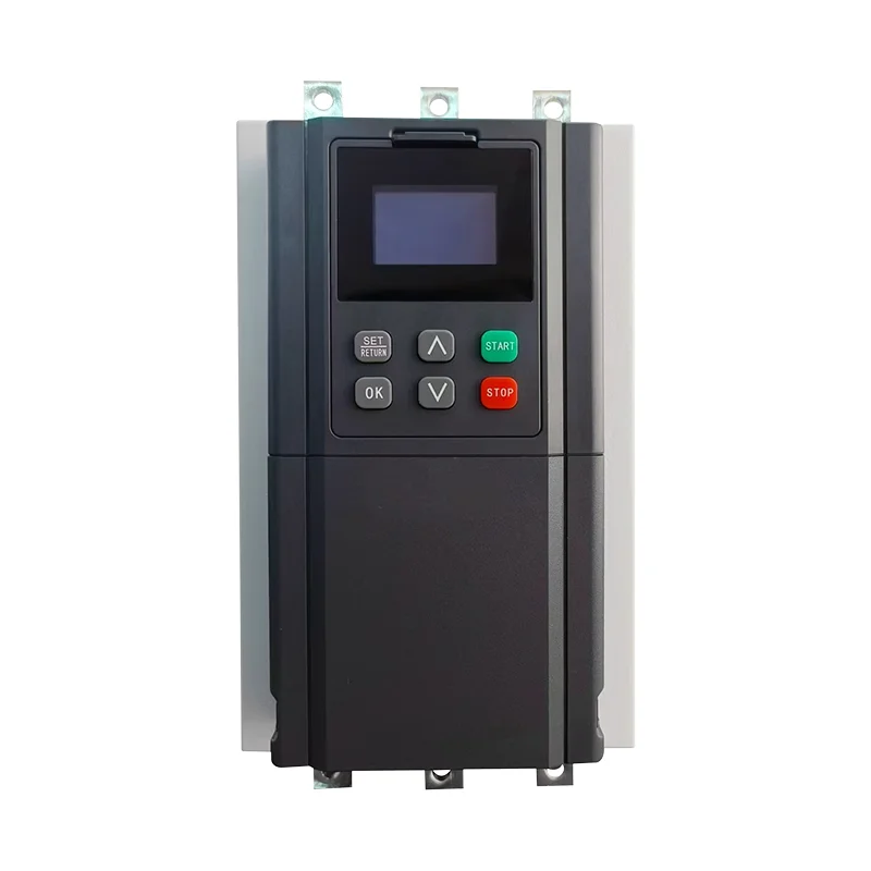
The NR1000 product page describes a built-in bypass arrangement. That does not justify assuming that the installed assembly has an externally accessible bypass contactor or that its contacts may be forced manually. For external designs, use the bypass contactor selection and verification guide alongside the exact schematic. Confirm the actual architecture before interpreting a transfer-related event.
Use the trip timing to organize the next check
This qualitative table is an investigation aid, not a fault-code decoder. Its categories organize supply, motor-path and operating-state evidence; the motor-protection context comes from Natural Resources Canada and the supply-quality considerations from the DOE source above. Exact detection thresholds remain model-specific.
| Event timing | Evidence to preserve | Investigation boundary | Unsafe assumption to avoid |
|---|---|---|---|
| Before a start command | Exact code and control-supply history | Manual-defined prestart detection conditions | Assuming every design checks phases while stopped |
| Immediately after command | Run signal, contactor sequence and phase records | Incoming path and connected motor circuit | Repeatedly resetting until the motor starts |
| During acceleration | Current traces, load state and acceleration record | Supply behavior, motor connection and starter path | Increasing current limits without diagnosis |
| At bypass transfer | Transfer command, feedback and current continuity | Actual bypass architecture and sequence | Forcing bypass contacts closed |
| During steady running | Prior events and simultaneous upstream records | Supply disturbance, connection condition and run path | Treating a keypad snapshot as a complete history |
Verify the cause and document return to service
A useful corrective record names the failed boundary and the evidence supporting it. Examples include an identified damaged connection repaired under the approved procedure or a documented upstream supply fault corrected by the responsible team. If the cause remains unconfirmed, keep the diagnosis open and define the next monitored test rather than writing “starter faulty” without supporting evidence.
Before a controlled return to service, confirm the approved settings, motor data, protection availability and the removal of temporary test arrangements. Inspect the affected circuit, obtain the required authorization and agree the process conditions for the trial. Observe the complete relevant sequence, including transfer and steady operation when those states were associated with the complaint.
Close the issue with as-found and as-left records, not simply an absence of alarms for a few seconds. Give LINECOME the exact model, motor nameplate, circuit diagram, fault history, trip timing and qualified measurements when requesting support. Identify which observations are verified and which remain assumptions so the response can address the actual installation.
Further learning: why three phases matter
The Engineering Mindset lesson below explains the three-phase supply concept. It supports the terminology used in the investigation, but it is not a procedure for live testing or soft-starter component repair.
Video by The Engineering Mindset. Watch How Three Phase Electricity works – The basics explained on YouTube.
Frequently asked questions
Does a phase-loss alarm prove that the utility supply is faulty?
No. Depending on the starter’s detection method, the indication may involve the incoming path, motor connections, load sensing or operating state. Use the exact manual and preserve the event timeline.
Can I disable phase-loss protection to confirm the diagnosis?
Do not bypass protection as a troubleshooting shortcut. A qualified specialist should select an approved test method that preserves the required protective functions and controls the process risks.
Why does the fault appear only when bypass takes over?
That timing makes the actual transfer sequence and current path important evidence. Check the installed architecture, commands, feedback and connections before concluding that the bypass device itself has failed.


