




A VFD long motor cable needs a system review, not a universal distance limit. Before ordering an output filter, identify the complete cable route, the motor insulation capability, the drive’s permitted output arrangement and the proposed filter’s operating envelope. Fast switching pulses can produce reflected-wave voltage stress at the motor even when the drive display shows normal voltage and current. A successful review ends with written compatibility evidence for the actual installation and a defined acceptance test. It does not end with a filter selected only by motor kilowatts.
This guide is for industrial buyers and commissioning teams comparing long-cable proposals. It is not a live-testing procedure. Qualified personnel must apply the equipment instructions, isolation arrangements and applicable electrical rules.
Why cable distance changes the output-side question
A drive supplies switched voltage pulses rather than the utility’s smooth sinusoidal waveform. At sufficiently fast pulse edges, the cable and motor behave as a transmission system. A mismatch in their electrical characteristics allows reflections. Incident and reflected pulses can combine, increasing the instantaneous voltage experienced at the motor terminals.
The ASHRAE chapter on motors and variable-frequency drives identifies cable type, distance and switching behavior as relevant variables. Its discussion also explains why a multi-motor output needs consideration of the connected cable network. Those principles explain the risk; they do not establish an approved cable length for a particular LINECOME model.
Do not confuse the drive’s output frequency, which controls motor speed, with its switching frequency. A slowly rotating motor can still receive fast switching edges. Likewise, a normal average voltage reading cannot establish the magnitude of a brief terminal-voltage peak. Our explanation of how a VFD works provides the broader operating context.
Make an installation record before comparing filters
Start with the installed route rather than the straight-line distance on a building drawing. Include vertical rises, detours, flexible connections and existing junction points. State whether the route is measured or estimated. Mark sections that cannot yet be inspected and assign someone to confirm them before purchase approval.
Record the cable manufacturer, construction, conductor size, shielding arrangement, number of parallel runs and termination method. Obtain the cable data sheet rather than assuming that every cable advertised for motor service has the same pulse-voltage or environmental capability. Cable sizing for current and voltage drop remains necessary, but it answers a different question from pulse insulation stress.
Next, identify the motor by its complete nameplate and serial number. Ask for the manufacturer’s suitability statement for inverter operation, including any restrictions associated with its insulation system, age, repair history or terminal accessories. An old rewound motor deserves an explicit review; its present capability should not be inferred from the original catalog.
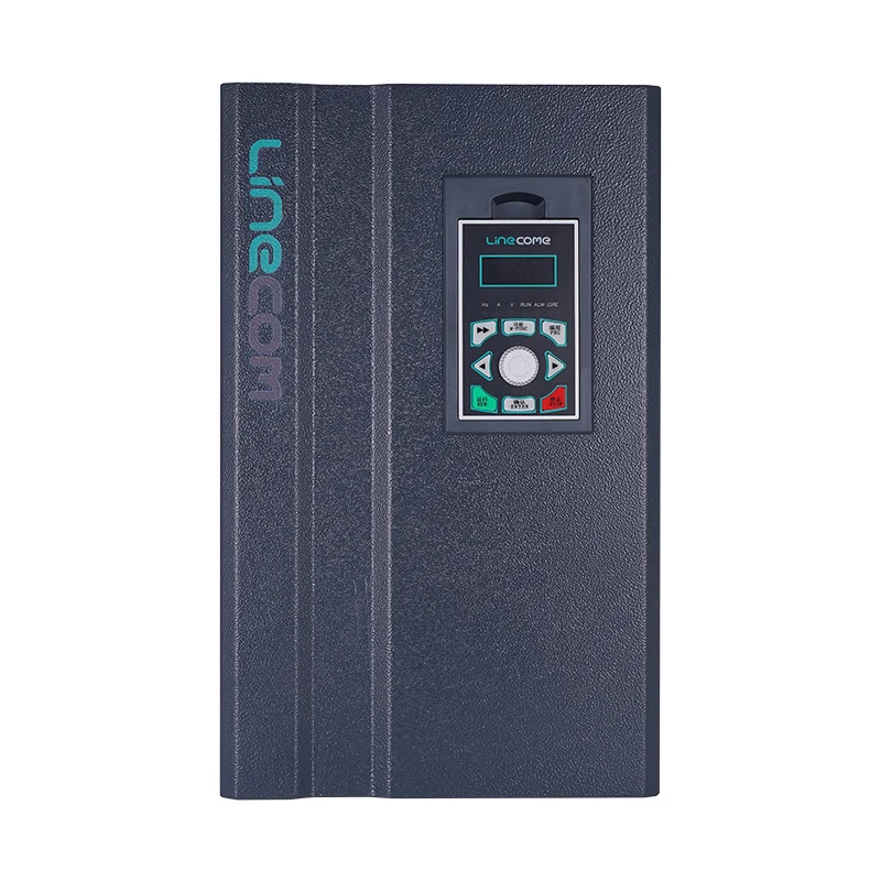
The original LINECOME product photograph illustrates a related drive frame size. It does not show a tested cable route, an installed output filter or the insulation capability of a connected motor. Keep these project-specific items in the written proposal.
Separate reflected waves from other long-cable problems
Long cable runs can raise several concerns, and one accessory may not resolve all of them. The investigation should distinguish motor-terminal pulse stress, cable charging effects, protective-earth current, electromagnetic interference and ordinary voltage drop. If the complaint is a noisy sensor signal, begin by identifying the signal path rather than immediately attributing it to motor insulation stress.
Fluke’s discussion of VFD motor-cable length explains why motor-terminal measurements can reveal stress that is not obvious from the drive end. Its measurement examples illustrate a phenomenon, not a pass threshold for every motor. Use acceptance limits approved for the actual motor, cable and drive combination.
Also distinguish this issue from DC-bus overvoltage during deceleration. The location of the excessive voltage, the operating event and the evidence required are different. A braking accessory intended for regenerative energy does not automatically solve output-cable reflections. Record the exact fault description before selecting a remedy.
Use a decision checklist with explicit boundaries
The following is a procurement checklist derived from the output-side issues discussed by ASHRAE and Fluke. It contains no universal length or voltage limits. The supplier must populate the missing project values and approve the proposed arrangement.
| Review item | Evidence to collect | Decision that evidence supports |
|---|---|---|
| Actual cable route | Measured installed length and branch layout | Whether the proposed output arrangement falls within documented limits |
| Cable construction | Manufacturer data and termination details | Compatibility with the switching waveform and installation environment |
| Motor insulation | Exact motor identification and inverter-operation statement | Whether terminal pulse stress needs additional mitigation |
| Output accessory | Model, continuous current, frequency range and application instructions | Whether the accessory is approved for this drive and load |
| Multiple motors | Branch lengths, motor data and individual protection design | Whether a single-motor recommendation remains applicable |
| Acceptance method | Approved measurement plan and written criteria | How the installed system will be accepted without guesswork |
A proposal that leaves a cell blank is not necessarily unusable, but it is incomplete. Mark the unresolved item and its owner. Do not turn an unanswered question into an assumed approval merely because the equipment is urgently needed.
Compare output reactors, dV/dt filters and sine-wave filters
These accessory names describe different approaches, and catalog terminology can vary. Request the exact performance statement for the proposed part. Ask which output issue it addresses, what waveform characteristics it changes and what conditions were used to establish its cable-length recommendation.
An output reactor should not be treated as interchangeable with every dV/dt filter. A dV/dt filter should not be assumed to deliver the same waveform as a sine-wave filter. Require the accessory manufacturer to state suitability for the drive’s switching behavior, motor current, output frequency and cable arrangement. Include any restrictions on control mode or parameter settings.
Evaluate the practical installation as well. Ask about losses, ventilation, enclosure space, ambient conditions, mounting orientation, maintenance access and the additional wiring required. A filter that meets an electrical objective but cannot dissipate heat in the proposed cabinet is not an acceptable finished solution.
Do not substitute an input-side line reactor or an input EMC filter without an explicit output-side application approval. Similar appearance does not establish suitability. Have the supplier identify the accessory position on the project drawing and reconcile it with the drive and motor documentation.
Treat parameter changes as controlled engineering changes
Changing switching frequency may alter several aspects of system behavior. It is not proof that an existing motor has become protected. Compare the manufacturer’s permitted settings and any drive-current derating with the proposed accessory instructions. Document both the original and proposed values.
Our carrier-frequency selection guide discusses the broader noise and operating tradeoffs. For the long-cable review, the narrower question is whether the complete system remains within its approved envelope after a change. Keep the insulation review separate from an operator’s preference for quieter operation.
If a supplier recommends a parameter change, request a reason, the expected result and the acceptance evidence. Avoid changing several variables together during troubleshooting. Otherwise a temporary improvement cannot be attributed to a specific correction, and future maintenance staff will inherit an undocumented configuration.
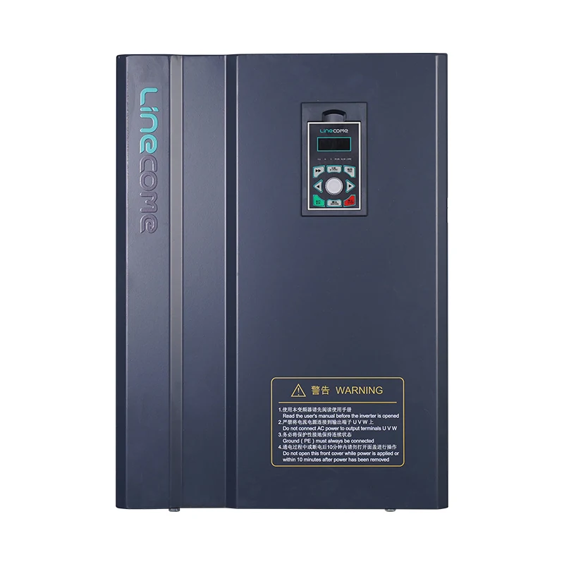
A larger drive frame is shown as a product reference, not as a recommended upgrade. Increasing drive size alone does not establish acceptable motor-terminal pulse voltage. Confirm the application with the actual equipment records.
Plan measurements without creating a new hazard
Motor-output testing involves hazardous voltages and fast waveforms. Measurement equipment, probes, connection methods and personnel competence must be appropriate to the task. A general-purpose meter reading cannot replace the agreed pulse-measurement method. Do not connect an ordinary grounded oscilloscope to a drive output as an improvised check.
HSE’s introduction to electrical safety emphasizes suitable equipment, maintenance and competent people. Use that safety principle when commissioning measurement work; the responsible engineer must define the specific method and isolation arrangements for the installation.
Specify where readings will be taken, the operating conditions to be represented and the information saved with each capture. Include the motor, cable and filter identities, relevant drive settings and instrument details. Ask for actual recorded evidence rather than a photograph of an instrument without its configuration or measurement location.
If the required testing cannot be done safely on site, resolve the verification method with the responsible suppliers before energization. An inaccessible terminal box is a planning constraint, not permission to infer the motor waveform from an unrelated measurement.
What to send LINECOME with an inquiry
For a project using the LNC860S vector VFD, submit the motor nameplate, load description, complete route length, cable data, supply information and proposed output accessory. State whether the installation is new, a retrofit or a repair. Include any existing fault history and the operating event associated with it.
Request a written response covering permitted cable arrangement, accessory compatibility, relevant settings and acceptance responsibilities. The product page identifies the drive family; it is not a long-cable approval for every installation. Our VFD installation guide covers surrounding installation questions that should be reviewed alongside this narrower output-system assessment.
Before ordering, agree who supplies the filter, who checks the motor insulation evidence and who signs the acceptance record. This avoids a common handover gap in which each vendor assumes another party approved the complete drive-to-motor system.
Educational video: understand the switched waveform
The Afrotechmods tutorial below explains pulse-width modulation using low-voltage examples. It helps distinguish pulse timing from an averaged electrical value. Its demonstration circuit is not an industrial VFD design, a reflected-wave test method or a cable-length recommendation.
Video by Afrotechmods. Watch What is PWM? Pulse Width Modulation tutorial! on YouTube.
Frequently asked questions
What is the maximum motor cable length for a VFD?
There is no single limit for all drives and motors. Obtain the permitted arrangement for the exact drive, cable, motor, switching settings and output accessory. A distance quoted for another product is a research clue, not an installation approval.
Does a normal drive voltage reading rule out reflected-wave stress?
No. A displayed or averaged value does not establish the peak and rise time of fast pulses at the motor terminals. Use the agreed measurement method and motor-specific acceptance criteria when verification is required.
Can an input reactor replace a motor-output filter?
Only if its manufacturer explicitly approves that application and the complete system is checked. Input and output accessories serve different positions and purposes. Do not transfer an accessory solely because its current rating or appearance seems suitable.


