




VFD braking resistor sizing requires four checks: the drive’s permitted resistance range, peak braking power, energy per braking event, and heat dissipation over the complete duty cycle. Motor kilowatts alone cannot determine a suitable resistor. Start with the exact drive and braking-unit documentation, calculate what the load returns during deceleration or lowering, and then verify the resistor’s pulse-energy and continuous ratings. For hoists, also confirm the mechanical brake and fault response separately: a braking resistor absorbs energy while the motor turns; it does not hold a suspended load after power is removed.
This guide develops the braking component of a drive specification. For the wider application, see our guide to VFD-controlled electric hoists. The calculations below are illustrative engineering examples, not approved resistor values for any LINECOME model.
Why a motor can send energy back into the drive
During normal motoring, electrical energy becomes mechanical work. During deceleration, a rotating load may drive the motor instead. A descending overhauling load can do the same throughout lowering. The inverter transfers that generated energy into the DC link. In a drive with an ordinary diode input rectifier, that energy cannot simply flow back into the utility supply through the rectifier.
A compatible braking chopper switches a resistor across the DC link when its control threshold is reached. The resistor converts electrical energy into heat. A regenerative supply unit provides a different path back to the supply, where that architecture is suitable. Neither arrangement should be assumed from the words “vector control.” Our explanation of a VFD’s power stages provides the background to that distinction.
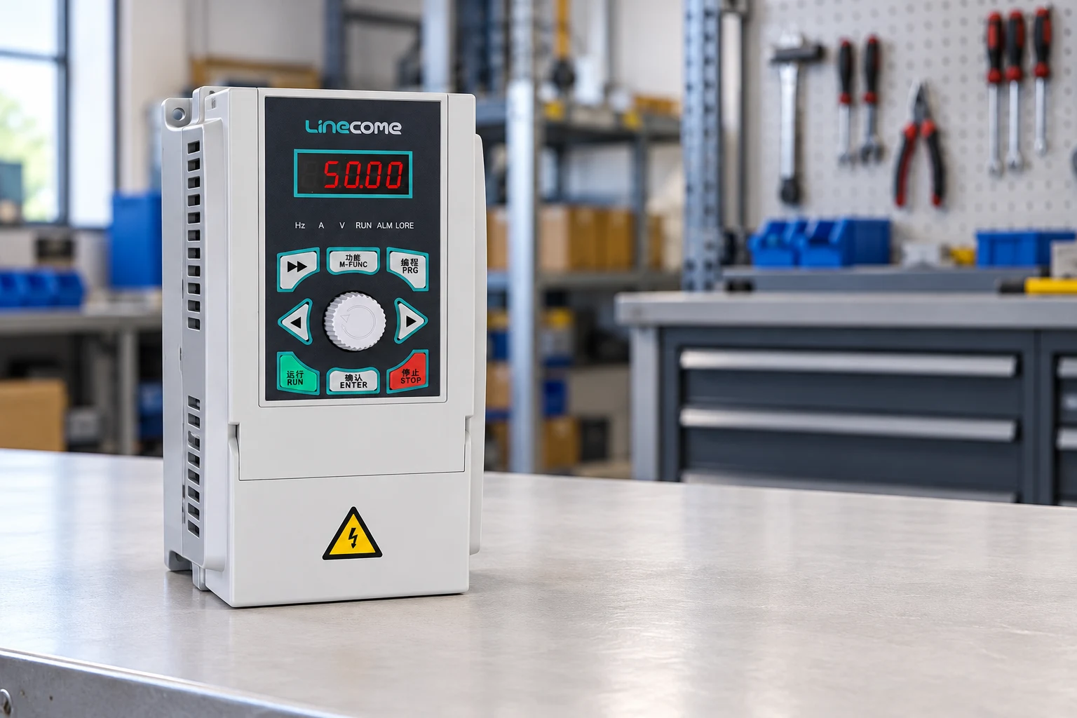
Collect these inputs before calculating ohms or watts
| Input | What to obtain | Why it matters |
|---|---|---|
| Exact drive and brake unit | Model, voltage class, installed options and manual revision | Determines permitted resistance, current and braking duty |
| Speed and inertia | Initial/final rpm and total inertia referred to the motor shaft | Determines rotational energy released |
| Vertical load | Moving mass, lowering height, speed and cycle sequence | Identifies sustained gravitational energy input |
| Timing | Deceleration time, lowering time and shortest repeated cycle | Separates pulse demand from average heating |
| Environment | Ambient temperature, enclosure, ventilation and mounting position | Determines thermal derating and safe installation |
| Protection | Resistor thermal contact and approved fault-interlock design | Defines response to overheating and brake-unit faults |
This is an information checklist, not a table of universal component ratings. Obtain the minimum resistance and allowable braking current from the installed drive’s own documentation. A catalog example for a different frame, supply voltage or brake option cannot substitute for it.
Step 1: establish the permitted resistance window
The resistor must remain within the braking unit’s permitted resistance limits, including component tolerance and temperature effects where specified. Too little resistance draws excessive chopper current. Too much resistance can limit the instantaneous power available to absorb energy, allowing the bus voltage to rise during the demanded stop. Increasing the resistor’s watt rating does not correct an unsuitable resistance value.
At an assumed chopper-on voltage V, the instantaneous electrical relationships are I = V/R and P = V²/R. Here V is in volts, R in ohms, I in amperes and P in watts. These relationships follow the circuit principles described in OpenStax’s explanation of resistance and Ohm’s law. They describe the electrical loading when the chopper conducts; they do not establish its permissible current.
For example, at a hypothetical 700 V switching level, a 100 Ω resistor would draw 7 A and dissipate 4.9 kW while connected. Those numbers are an arithmetic illustration only. The actual switching threshold varies by equipment. Do not use nominal AC supply voltage in place of the documented DC switching voltage, and do not treat 100 Ω as a suggested selection.
Step 2: estimate the braking energy
Rotating machinery stopping from speed
For a rotating load, the change in kinetic energy is E = ½J(ω₁² − ω₂²), with inertia J in kg·m² and angular speed ω in rad/s. Convert rpm using ω = 2πn/60. Include motor inertia and all relevant load inertia referred consistently to the motor shaft. Gear ratios affect reflected inertia by the square of the speed ratio; mixing load-shaft inertia with motor-shaft speed produces a large error.
The energy relationship is explained in OpenStax’s rotational kinetic energy chapter. Mechanical losses may reduce energy reaching the drive, but optimistic loss assumptions can understate resistor demand. Use documented efficiency information or a conservative, clearly stated preliminary assumption.
Lowering or other overhauling duty
A descending mass releases gravitational potential energy, approximately E = mgh, with mass m in kilograms, g approximately 9.81 m/s² and vertical travel h in metres. The amount reaching the resistor depends on the mechanical transmission, motor and inverter losses. Include the hook block and other moving mass that belongs in the load calculation. Avoid counting the same translational energy again through a reflected model.
A hoist can regenerate during steady-speed lowering, not just during the final deceleration. An estimate that includes a two-second stop but ignores twenty seconds of lowering misses the dominant thermal event. Use the complete motion sequence, including repeated positioning movements and the heaviest credible production pattern.
Step 3: separate average braking power from peak demand
Consider an illustrative horizontal rotating load with total motor-shaft inertia of 2 kg·m². It slows from 1,500 rpm to zero in five seconds, once every sixty seconds. Initial angular speed is approximately 157.08 rad/s. Stored rotational energy is therefore approximately 24.67 kJ. Ignoring losses for this preliminary example, average power during the stop is 24.67 kJ / 5 s = 4.93 kW.
The cycle-average thermal load is 24.67 kJ / 60 s = 0.411 kW. These two power figures serve different purposes. The lower cycle average does not mean that an ordinary 411 W resistor can accept the braking pulse. Its manufacturer must permit at least the required pulse energy at the specified duration, repetition rate, ambient temperature and mounting condition.
For a linear speed ramp with approximately constant braking torque and no significant external load torque, mechanical braking power is greatest at the beginning and decreases with speed. In this simplified example, initial power is approximately twice the event average, or 9.87 kW. Real torque profiles and chopper switching change instantaneous electrical demand. Check the drive’s braking current and the resistor’s overload curve rather than sizing only from the five-second average.
Step 4: check pulse capacity and repeated heating together
Duty cycle is braking time divided by total cycle time. The example has a nominal braking duty of 5/60, or 8.33%. That percentage says nothing by itself about the energy of each event. Two machines can both operate at 8.33% duty while demanding very different peak power and pulse energy.
For several braking segments, add their energies and divide by the complete repeating cycle time to estimate average heat. Then check each pulse and the sequence against the resistor supplier’s thermal data. Closely spaced stops may accumulate heat before the resistor has recovered. A production shift with shorter cycles than the original quotation can invalidate an otherwise correct selection.
Continuous or frequent lowering can make regenerative equipment worth evaluating. Compare installation cost, heat rejection, supply compatibility and operating pattern. A resistor dissipates recovered mechanical energy as heat; it does not return that energy to the electricity bill as useful electrical savings.
Thermal protection and mechanical holding are separate requirements
A resistor can become dangerously hot even when the motor is lightly loaded during other parts of its cycle. Follow the component supplier’s mounting orientation, clearances, enclosure and cable requirements. Keep heat away from drive cooling inlets, control wiring and combustible material. A thermal contact needs an engineered response; connecting it to an ordinary software stop input is not automatically sufficient for every fault or lifting application.
For US overhead and gantry cranes within its scope, OSHA 1910.179 addresses holding brakes and control braking. Applicable requirements depend on the crane and jurisdiction. Brake coordination, stopping distance and power-loss behavior belong in the machine design and commissioning plan. A resistor does not provide a mechanical holding function, and a drive’s stop command should not be described as proof that a suspended load is secure.
What to send with a LINECOME braking enquiry
Use the LNC860S vector VFD range as a starting point for a model discussion, then request written confirmation of the exact brake-unit arrangement. Do not infer an installed braking option, resistor resistance or hoist safety capability from the series name. Compare other drive families through the LINECOME product hub if the application requires a different voltage or current class.
Send the motor nameplate, drive model, supply voltage, inertia estimate, load and gearbox data, motion profile, required stopping time, cycles per hour and site temperature. Request the permitted resistance, pulse-energy requirement, continuous dissipation, thermal protection scheme and acceptance procedure as separate quotation fields. Before site work, use the broader VFD installation checklist to coordinate grounding, protection and commissioning responsibilities.
Further learning: the drive’s DC link and inverter
The Engineering Mindset’s independent educational video explains the rectifier, DC link and inverter. It helps readers locate the energy path discussed above; it is not a resistor-sizing instruction or approval for a particular machine.
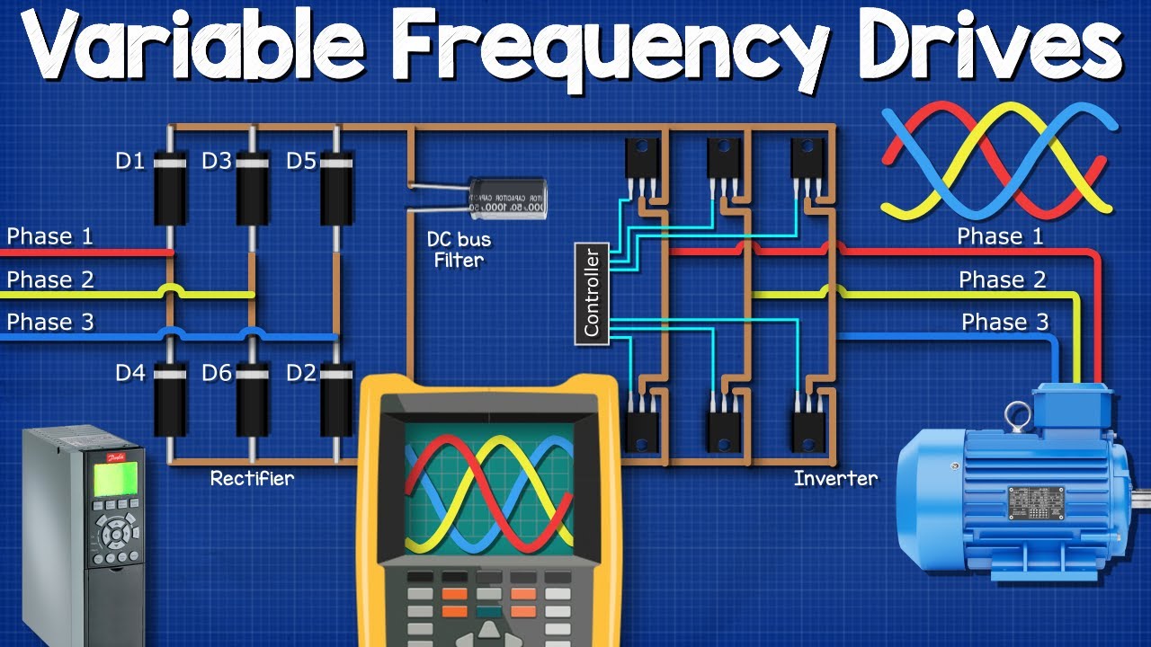
Watch the VFD explanation on YouTube.
Frequently asked questions
Can I size a braking resistor from motor horsepower alone?
No. Motor power does not describe load inertia, lowering energy, required stop time or repeated thermal demand. Use the drive limits and the complete load cycle.
Does a higher wattage permit a lower resistance?
No. Resistance controls chopper current at a given voltage. Wattage and pulse-energy ratings describe thermal capacity. Both must satisfy the equipment documentation independently.
Will a braking resistor hold a hoist when power fails?
No. It dissipates generated energy during motion. Mechanical holding and power-loss response require the appropriate brake system and machine-level design.
Is an overvoltage trip proof that the resistor is too small?
No. The cause may include a missing or disabled brake unit, unsuitable resistance, wiring faults, supply conditions or an unrealistic deceleration command. Diagnose the complete system before changing components.
Related practical guides
If the drive is already tripping, start with our VFD overvoltage troubleshooting guide to distinguish supply-related events from regenerated energy before selecting or replacing a braking resistor.


