




A VFD input line reactor adds series inductance on the supply side of a drive. It can help manage rectifier current distortion and some supply disturbances, but selecting one requires the exact drive input data, existing supply impedance and available voltage margin. Start by identifying the problem and the electrical location where it occurs. Then check whether the drive already contains an AC choke or DC-link reactor. An accessory selected from motor kilowatts alone can miss the actual input current, overload duty, installation conditions or intended power-quality objective.
Establish the input-side problem
Write a short requirement that can be verified. Examples include following a documented drive-manufacturer requirement for a strong supply, reducing measured input-current distortion or investigating trips associated with a recorded supply event. State where voltage and current were measured and which other loads were operating. A reactor cannot be selected reliably from an unexplained statement that the system has electrical noise.
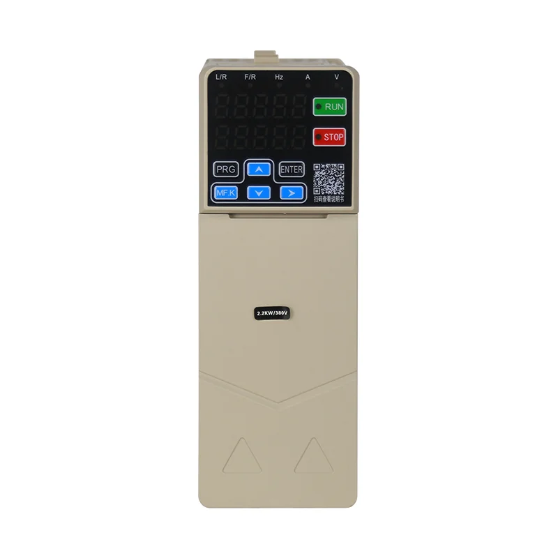
The LNC610 general-purpose VFD is a relevant product starting point for an input-accessory inquiry. Confirm the exact ordered model and its input arrangement with the supplier. The product family name or enclosure photograph does not establish the presence of an internal choke, a permitted external impedance or a site harmonic result.
Review the drive power-stage explanation if the input and output boundaries are unclear. The supply feeds a conversion stage and DC link, while the inverter generates the motor-side waveform. These stages present different engineering questions. Record the terminals and circuit location on a one-line diagram before adding an accessory to the order.
Distinguish input reactors, DC chokes and output equipment
An input AC reactor is installed in the drive supply circuit in accordance with the approved arrangement. A DC choke is part of the DC-link circuit where supported by the drive design. Both can affect input-current behavior, but they have different connections and cannot be treated as interchangeable field wiring options.
An output reactor or motor-side filter addresses conditions between the inverter and motor. Cable length, pulse edges and motor insulation enter that separate review. If the actual concern is a remote motor or reflected-wave stress, start with the VFD long motor cable guide and the drive manufacturer’s motor-side accessory instructions.
The ASHRAE chapter on motors, motor controls and variable-frequency drives explains input harmonics and distinguishes them from motor-side PWM effects. It also discusses how AC-line and DC-bus reactors affect the input circuit. These distinctions provide a useful basis for asking the right supplier questions without transferring one accessory’s purpose to another location.
Build the supply and drive data sheet
Collect nominal supply voltage, frequency, permitted variation, transformer information, upstream protective devices and the relevant distribution arrangement. Identify other significant nonlinear loads and any existing capacitors, filters or power-conditioning equipment. A reactor is part of a connected system, so its review should include the equipment on both sides.
For the drive, collect the exact input rating, current under the intended duty, overload requirements, internal impedance information and accessory restrictions. Use input-side data for the input reactor review. Motor nameplate current and drive output current answer related questions, but they do not automatically establish the accessory’s required supply-side rating.
Record installation temperature, enclosure ventilation, mounting orientation, available space and connection requirements. Ask how the reactor’s losses enter the cabinet thermal calculation and whether its specified current capability changes under the installation conditions. A suitable electrical selection still needs an acceptable mechanical and thermal installation.
Where supply fault-current information or protection coordination is required, obtain it through the project electrical design. Adding a reactor should not be assumed to establish the interrupting rating or short-circuit rating of the assembly. The responsible designer must evaluate those requirements using the applicable equipment and method.
Interpret impedance ratings with their stated base
A percentage impedance rating is meaningful only with its specified voltage, current and frequency base. Ask the supplier to state those bases and the permitted operating range. Compare proposed options using the same basis before deciding that one has more or less impedance than another.
For an ideal inductance, its sinusoidal reactance is Xₗ = 2πfL, where Xₗ is ohms, f is hertz and L is henries. As an illustration, a 1.0 mH inductance at 50 Hz has a reactance of approximately 0.314 Ω. This is a basic circuit calculation using assumed values. It does not define a suitable reactor for any LNC610 model.
The actual drive input current is nonsinusoidal, and the resulting voltage behavior depends on the full circuit. Multiplying a catalog impedance percentage directly by line voltage and calling the result the exact operating voltage loss can therefore mislead the selection. Ask for the accessory manufacturer’s voltage-drop and performance data under the intended duty, then check the remaining drive input margin.
Also consider the lowest expected supply condition. An accessory that is acceptable at nominal voltage may leave insufficient operating margin during a site voltage dip. Record the minimum supply assumption and review it with the drive supplier before the equipment is ordered.
Use a decision table tied to the evidence
The following table organizes the review. Its entries are qualitative engineering questions, not promised harmonic reductions or universal installation rules. The drive documentation and measured site conditions determine the final decision.
| Project condition | Evidence to collect | Selection question |
|---|---|---|
| Drive manual requires external input impedance | Exact model instructions and existing source data | Which approved accessory and installation conditions satisfy the requirement? |
| Input-current distortion is the concern | Waveforms, load level and measurement location | What improvement is supported for this drive and supply? |
| Supply voltage is already low | Minimum voltage record and drive operating range | Does the proposed accessory preserve enough input margin? |
| Drive already contains a choke | Internal circuit description and supplier confirmation | Is additional impedance needed and permitted? |
| Motor cable stress is the concern | Cable route, motor data and output restrictions | Is a motor-side solution required instead? |
| Many drives share a supply | Combined load profile and system assessment | Should mitigation be assessed at the common system level? |
Set realistic harmonic acceptance criteria
A reactor can change the shape and magnitude of input current, but a particular impedance percentage does not establish a universal distortion result. Drive loading, rectifier design and existing source impedance all matter. A result from one drive frame or test supply cannot simply be assigned to a different installation.
The US Department of Energy electrical-systems reference guide includes inductive reactance among the measures used to address VFD-related harmonics and supply disturbances. Treat that guidance as technical background. Its example recommendations still require reconciliation with the current drive documentation and the actual site arrangement.
Agree the measurement point before writing a harmonic limit into the order. A drive input terminal and the facility’s point of common coupling represent different boundaries. The assessment may need to include several loads rather than the drive alone. Identify the applicable standard edition and responsibility for the system assessment instead of accepting a general claim that one accessory guarantees compliance.
For before-and-after comparison, record instrument settings, load level, operating drives and the relevant supply condition. Compare like operating states. A lower current-distortion percentage at a different load is not enough evidence to attribute the change solely to the reactor.
Coordinate installation and protection
Use the approved one-line diagram and equipment instructions to establish connection order, protective devices and isolation points. Confirm that the reactor is suitable for the drive supply configuration. Do not connect a supply-side accessory to the inverter output unless that exact use is expressly supported by the relevant manufacturers.
The VFD installation guide places incoming connections, protective bonding and commissioning in the wider installation process. For the added reactor, include terminal preparation, conductor ratings, tightening requirements, mechanical support and heat clearance in that same controlled work package. Inspect the installed arrangement against the revised drawings before energizing.
The HSE maintenance guidance supports planned isolation and management of stored energy for this work. A drive can retain hazardous energy after its supply is disconnected. Follow the exact discharge and verification instructions for the installed equipment, and control restart permissions during testing.
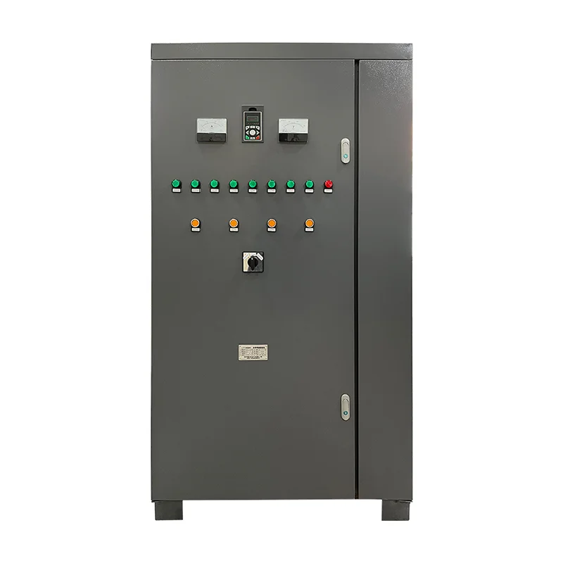
A cabinet photograph can help discuss space and equipment arrangement with the supplier. It does not show an approved reactor location or prove that the pictured cabinet contains one. Specify the proposed equipment, losses and clearances so the cabinet builder can evaluate the actual enclosure design.
Request a complete accessory proposal
Send the supplier the drive model, input data, supply conditions, intended duty and the measured problem. Request the reactor’s exact reference, voltage and frequency rating, current capability, impedance basis, overload suitability, losses, dimensions and installation requirements. Include the expected operating temperature and enclosure arrangement.
Ask what performance evidence supports the recommendation and which assumptions it depends on. If the objective concerns harmonics, ask for the modeled or measured operating point and the assessment boundary. If the objective concerns supply events, ask which event types the recommendation addresses and which require a separate investigation.
Define the acceptance test before delivery. Include normal running, the relevant load changes, minimum expected supply conditions where safely reproducible, and a review of drive diagnostics. Record input voltage, current behavior and thermal observations using the approved method. Retain any remaining system-level study requirement in the handover rather than treating workshop operation as final site acceptance.
Further learning about drive power stages
The Engineering Mindset lesson below explains the rectifier, DC link and inverter stages of a variable-frequency drive. It helps a project team identify which side of the drive an accessory belongs to. Apply the exact drive and reactor instructions when selecting and installing the project equipment.
Video by The Engineering Mindset. Watch Variable Frequency Drives Explained – VFD Basics IGBT inverter on YouTube.
Frequently asked questions
Does every VFD need an external input line reactor?
Review the exact drive instructions, existing source impedance and project objective. Some installations need an external accessory, while others already have suitable internal or upstream provisions. Confirm the intended arrangement with the equipment supplier.
Can an input reactor solve a long motor cable problem?
Long motor cable effects arise on the inverter output circuit and need a motor-side review. Confirm cable limits and approved output accessories for the exact drive and motor. An input reactor has a different circuit location and purpose.
Does a reactor percentage guarantee harmonic compliance?
The result depends on the drive, loading, supply impedance and measurement boundary. Specify the applicable assessment method and obtain evidence for the actual system. A catalog percentage alone does not establish the facility’s compliance result.


