




A VFD insulation resistance test should normally mean an offline test of the motor or cable after the drive electronics have been isolated from the test circuit. Do not apply an insulation tester through a connected variable frequency drive. First define the test boundary, identify every connected electronic device and obtain the approved motor, cable and instrument procedure. A useful result includes the test conditions and a documented return-to-service check, not just a resistance number.
This article helps maintenance teams plan the work and interpret the handover. It is not a terminal-by-terminal instruction for an unknown installation. Qualified personnel must select the test arrangement, voltage, duration and acceptance criteria for the actual equipment and local requirements.
Define what the test is intended to answer
Start with the maintenance question. A scheduled condition assessment, investigation after water ingress and diagnosis of a drive ground-fault event are different tasks. Record the symptom and the state of the machine before disconnecting anything. Preserve the drive fault history, motor identity and any recent repair or cable-routing changes.
Insulation resistance evaluates a particular insulation path under a specified DC test. It is different from measuring winding resistance with a low-resistance instrument, checking protective-conductor continuity or examining an operating current waveform. One favorable result does not replace the other checks needed for a safe machine.
Write the intended boundary on the drawing. “Motor circuit” is too vague if it could include the drive, output filter, cable, motor, temperature sensors and ancillary equipment. State which item is being tested and which items must be excluded. That decision makes subsequent readings interpretable and reduces the risk of exposing electronics to an unsuitable voltage.
Keep the drive outside the insulation-test circuit
Electronic equipment can provide unintended test paths and may be damaged by test voltage. Fluke’s sequential insulation-testing guidance emphasizes isolating electronic controls and other affected devices before insulation testing. Use that principle to review the complete installation, including components that are not obvious at the motor terminals.
Check for output filters, surge devices, sensing circuits, encoder connections, motor heaters and temperature-monitoring equipment. Their presence does not mean every accessory requires the same disconnection method. It means the competent person must consult the applicable drawings and instructions before deciding the test path. Do not infer that a device is protected because it is downstream of an open contactor.
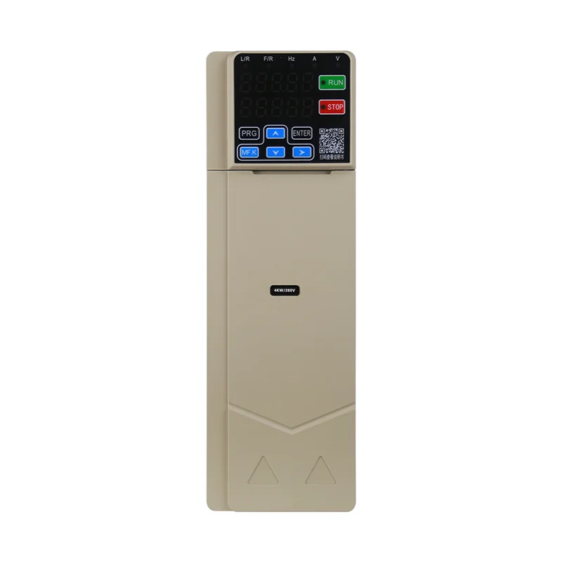
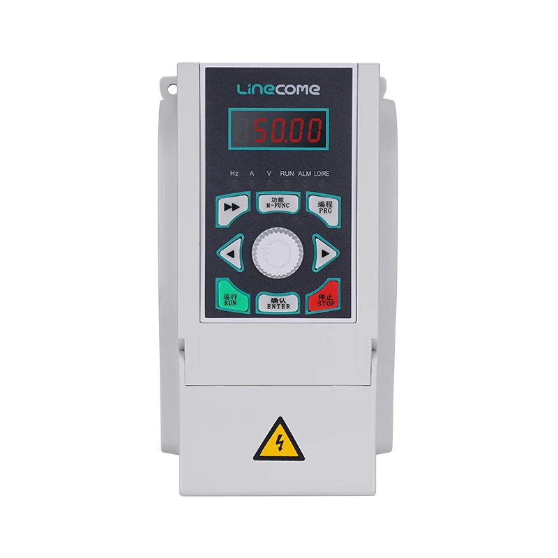
For a LINECOME LNC610 general-purpose VFD, obtain the exact supplied model’s instructions and cabinet drawing. The product page identifies the series and application context; it does not authorize a particular insulation-test voltage across its terminals. If an equipment manual permits a special test on the drive itself, treat that as a separate manufacturer-specific procedure rather than extending this motor-and-cable guide.
Plan isolation and stored-energy control
Stopping the motor from a keypad is not the same as making the installation safe for work. Identify the incoming supply, separate control supplies, shared circuits and any other source that can energize the equipment. Consider mechanically driven rotation or process energy where relevant. A motor can be part of a larger machine whose hazards remain after an electrical stop.
HSE’s guidance on electrical work explains the need for secure isolation and competent planning. Follow the site’s approved lockout, verification and access arrangements. Use the discharge interval and verification method stated for the actual drive; this article deliberately does not substitute a universal waiting time.
The insulation test itself can charge the item under test. Include the instrument manufacturer’s discharge procedure and confirmation that the circuit is safe before handling or reconnection. Automatic discharge features do not remove the need to understand the instrument’s instructions. Assign responsibility for controlling access to disconnected conductors and for confirming the end of the test.
Choose a boundary that localizes the problem
A combined motor-and-cable reading can be useful within an approved procedure, but it describes the combined path. A poor result does not identify whether the motor, cable, termination or contamination is responsible. Plan how a follow-up test would separate those possibilities before beginning a long sequence of disconnections.
For a cable-only assessment, the procedure must establish the required separation from equipment at both ends and account for every connected branch. For a motor-only assessment, the motor instructions govern connections, accessories and any terminal-link arrangements. Do not copy a connection sketch from a different winding arrangement and assume that it applies.
Label conductors and photograph the approved original arrangement where site rules permit. Record terminal references, cable identification and any links removed during the work. The test record should make it possible for a second competent person to understand the boundary without guessing from a handwritten resistance value.
Record the conditions that make readings comparable
The following checklist identifies evidence to include in the approved work package. It draws on the isolation principle above and EASA’s motor insulation-test overview, which covers test selection, discharge and interpretation. It does not establish numerical acceptance limits for an unknown motor.
| Record field | Why it matters | Evidence to retain |
|---|---|---|
| Item and boundary | Identifies what the reading represents | Marked drawing and motor or cable identity |
| Excluded equipment | Shows electronics were outside the test path | Disconnection or isolation checklist |
| Instrument and leads | Supports confidence in the measurement | Instrument identity and applicable verification record |
| Test voltage and duration | Different conditions can produce different readings | Approved values and actual test settings |
| Temperature and relevant environment | Helps interpret changes between tests | Measured or documented conditions and correction method if used |
| Result and criterion | Separates observation from acceptance | Reading, units and source of the acceptance requirement |
| Discharge and restoration | Controls the transition back to service | Completion sign-off and reconnection record |
Avoid treating one threshold as universal
Acceptance depends on the motor or cable, its insulation system, condition, temperature and the applicable procedure. Do not copy a megohm value from an unrelated voltage class or equipment manual. A maintenance trend may provide additional context, but comparison is meaningful only when the test boundaries and conditions are sufficiently consistent.
A changed reading may reflect moisture, surface contamination, temperature or an altered measurement path. Record those possibilities instead of immediately declaring a winding failure. Where correction to a reference temperature is part of the approved motor procedure, retain the original observation and the correction basis. An unexplained adjusted number is difficult to audit later.
A high insulation resistance result also has limits. It does not establish that turn-to-turn insulation is healthy under every operating stress, that the cable installation is correct or that the protection system is suitable. State the specific test conclusion, then list the other checks required for release. That wording prevents a narrow electrical measurement from becoming an unsupported whole-machine approval.
Investigate a poor or inconsistent result methodically
Stop and review the setup before escalating the test. Confirm that the intended electronics are excluded, the correct item is identified and the leads and accessible termination surfaces are suitable for the procedure. An uncertain boundary is a reason to correct the work plan, not a reason to increase test voltage.
If authorized, separate cable and motor tests can help localize the issue. Compare the observations with inspection findings and maintenance history. A wet termination enclosure after washdown deserves a different investigation from a damaged cable along a moving machine axis. Any drying, cleaning, repair or further testing should follow the equipment supplier’s instructions and the site’s controlled process.
A drive trip during operation can remain unresolved even when a cold offline resistance test appears satisfactory. Record the operating conditions, fault timing and limitations of the offline result. Our VFD RCD investigation guide discusses residual-current protection compatibility, a separate question from insulation resistance. Do not use a favorable offline result to justify removing protective functions.
Restore the installation before a controlled run
Restoration should be an explicit part of the work package. Confirm discharge is complete, remove temporary test arrangements and reconnect each item against the approved drawing. Verify terminal identification, any removed links, accessories, protective connections and covers using the specified inspection and tightening requirements. Do not guess a torque value from terminal size or appearance.
Review the settings and fault record before returning control to the operator. The VFD installation checklist provides a broader handover context for wiring and commissioning. Where the fault investigation concerns a long motor cable, the reflected-wave review addresses operating stress and cable-related design questions that an offline resistance reading cannot settle.
Conduct the authorized functional check with the machine area controlled and the stopping arrangements confirmed. Record the operating conditions and whether the original symptom recurs. A test report is complete when its results, restoration checks and release decision can be traced together. Keep unresolved operating symptoms visible rather than closing the job solely because the instrument displayed a high value.
Prepare a useful service or supplier inquiry
Provide the exact drive and motor models, voltage class, cable type and approximate installed length, relevant accessories, fault history and the marked test boundary. Include the actual voltage, duration, conditions and readings from the approved test. State whether motor and cable were measured separately or together.
Ask the responsible supplier or repair facility which additional checks are appropriate for the observed symptoms. Avoid requesting a blanket declaration that the complete system is healthy based on a photograph of one meter screen. A clear evidence package makes it easier to distinguish insulation repair, cable work and drive-specific investigation without ordering unnecessary replacement equipment.
Further learning: insulation resistance principles
The John Ward educational video below introduces insulation resistance testing and common interpretation problems. It is useful background for understanding why test boundaries and connected equipment matter. Its installation examples do not replace the motor, cable, drive or instrument instructions for this project.
Video by John Ward (jwflame). Watch Insulation Resistance Testing on YouTube.
Frequently asked questions
Can I insulation-test the motor while it is connected to the VFD?
Do not apply test voltage through a connected drive. The qualified person must define and isolate the approved test boundary, exclude affected electronics and follow the motor, cable and instrument procedures before testing.
What insulation resistance value means the motor passes?
There is no single value that this article can approve for every motor. Use the applicable motor instructions and test procedure, record the test conditions and compare results only on a documented basis. The reading alone does not approve the whole machine.
Does a good result rule out every VFD ground fault?
No. An offline test evaluates a defined insulation path under particular conditions. It may not reproduce heat, moisture movement or operating stresses present during the fault. Preserve the operating evidence and investigate the remaining possibilities without defeating protection.


