




VFD RCD nuisance tripping should be investigated by identifying the device that operated, recording when it trips, and checking both real insulation faults and compatibility with the drive’s leakage-current waveform. Do not assume that repeated trips are harmless, and do not remove protective earthing or increase a trip setting simply to keep a motor running. A drive can create residual currents during normal operation, while a damaged cable can create a genuine fault. Distinguishing those situations requires the installation drawings, the exact drive and RCD documentation, and a competent electrical investigation.
This guide helps maintenance managers and panel buyers assemble that evidence. It does not prescribe a universal RCD type, sensitivity or wiring arrangement. Applicable installation rules, the earthing system and manufacturer instructions must determine the final protection design.
First establish whether the trip is actually residual-current protection
“The breaker trips” is an incomplete fault report. An upstream miniature circuit breaker may operate because of overcurrent. An RCCB operates on residual current without providing overload protection. An RCBO combines functions, so the indication and device documentation matter. A drive’s internal ground-fault alarm is another separate event. Record the device label, model, indication and position in the single-line diagram before discussing replacement parts.
Also distinguish a residual-current Type B device from an overcurrent breaker with a B tripping curve. The similar lettering describes different characteristics. The IET explanation of RCD types describes this distinction and the need to match residual-current protection to connected equipment. Its UK guidance provides useful principles; the project designer must confirm the current rules in the installation’s jurisdiction.
For a new inquiry, photograph the complete label rather than transcribing only “B” or the current rating. Include whether the device protects one drive, several drives or additional unrelated loads. That information can change the investigation before anyone opens the cabinet.
Explain why a healthy drive can still contribute leakage current
A drive is not electrically equivalent to a motor connected directly to the supply. Its input conversion stage, EMC components and switched output introduce additional paths and waveforms that protection selection must accommodate. The GAMBICA/REMA installation guide, particularly section 4.2.3, discusses filter-related and motor-circuit capacitive residual currents. It also warns that stored electrical charge can remain after an upstream trip.
That explanation does not prove a particular installation is healthy. A damaged motor lead, contamination or moisture must remain in the fault investigation. Use “suspected unwanted operation” in the initial report rather than declaring a nuisance trip as a diagnosis. The aim is to explain the observed event while retaining the required protection.
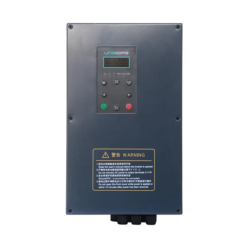
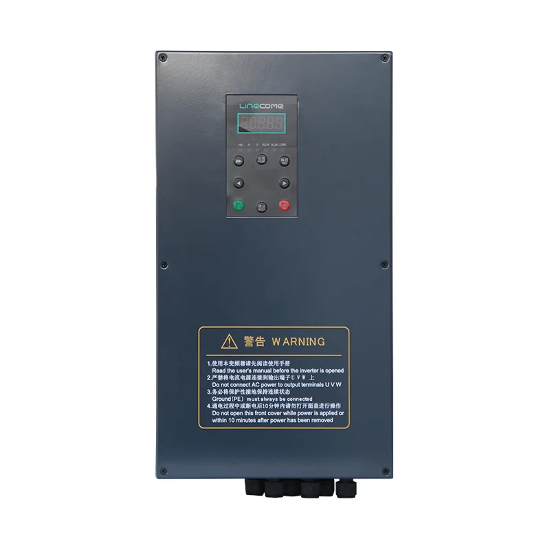
The LNC820D high-protection VFD is a relevant product family for discussing an enclosed drive installation. Its external enclosure does not establish which RCD is compatible, certify a complete circuit, or prove that an existing motor cable has adequate insulation. Request the exact supplied model’s installation documentation and protective-device requirements.
Build a timeline around energization, running and environmental changes
Separate supply energization from a run command. A trip as the cabinet receives power is a different observation from a trip only after the motor accelerates. Record whether the drive had started switching, whether other drives were energized at the same time and whether a recent modification preceded the first event. Do not repeatedly reset the installation to generate an informal test series.
Ask operators to record events they can safely observe: the time, operating mode, displayed alarm, commanded speed and weather or washdown history. Preserve the original alarm sequence before power cycling erases useful information. A photograph of an indication can be more valuable than a verbal report written at the end of a shift.
Review the change history with the same care. Was a longer motor cable fitted? Did a replacement EMC component enter service? Was a previously independent circuit grouped beneath one protective device? These are investigation prompts, not proof of causation. An electrician should connect each suspected cause to measurements or inspection findings before a correction is accepted.
Use a fault-evidence table to assign the next investigation
The following is a proposed investigation record, not a set of trip thresholds. Its purpose is to prevent purchasing decisions based only on a symptom. The physical mechanisms and protection distinctions are described in the GAMBICA and IET references above.
| Observation | Evidence to preserve | Question for the responsible specialist | What does not follow automatically |
|---|---|---|---|
| Trip when supply is energized | Device indication, energization sequence, connected loads | Are switching transients or a real fault responsible? | A larger trip setting is acceptable |
| Trip only when the motor runs | Speed, motor route, cable changes, alarm sequence | Does the measured residual-current behavior fit the protection and installation? | The motor must be defective |
| Trip after several drives start | Circuit grouping and individual operating states | Is shared residual current contributing to operation? | Protective earth should be disconnected |
| Trip after moisture exposure | Environmental timeline and inspection findings | Has insulation or enclosure integrity deteriorated? | The event is merely electrical noise |
| No trip after an undocumented change | Exact wiring and setting differences | Does the required protection still function? | Continued operation proves safety |
For each row, name an owner and a decision date. If the evidence is unavailable, record it as missing. A partially completed investigation sheet is preferable to an invented leakage value that later becomes the basis for equipment selection.
Review RCD compatibility without choosing from a letter alone
The protection designer needs the possible fault-current waveforms as well as normal operating residual currents. The IET discussion explains why DC components can affect unsuitable devices. A device that stops unwanted trips but cannot detect the relevant fault is not a satisfactory correction.
Obtain written compatibility information for the exact drive arrangement. Include input phase configuration, filters, motor circuit, shared loads and protective-device location. Do not copy the sensitivity or device recommendation from another manufacturer’s drive, another country’s installation or a single internet example. The required protection function may differ between those situations.
Review upstream and downstream devices together. A new branch device can affect selectivity or leave a shared upstream device exposed to a waveform it was not selected to handle. Ask for the updated protection schedule and the designer’s explanation of the complete arrangement, rather than a statement that one component is “VFD compatible.”
Set clear boundaries for measurements and insulation testing
Have a competent person plan the investigation and determine suitable instruments, connection points and isolation procedures. Measurements need an identified circuit and a known operating state. A current value without a measurement method, instrument capability or time reference is weak evidence for a protection decision.
Insulation testing must follow equipment instructions. Do not apply a test voltage through connected drive electronics because a generic motor test procedure appears familiar. The electrician should document what was isolated, what remained connected and which equipment-specific limits applied. This article deliberately provides no energized probing or terminal-bridging procedure.
The HSE guidance on electrically powered equipment emphasizes suitable equipment, competent advice and the limits of RCD protection. A tripped RCD is not proof that every source of hazardous energy has been isolated. Use the site’s safe working procedure before inspection or repair.
Keep earthing, EMC and continuity of service in the same design review
Removing a protective earth conductor is not an acceptable troubleshooting shortcut. Likewise, disconnecting an EMC component simply because trips disappear can change the installation’s compliance and interference behavior. A successful repair must preserve the required safety and EMC performance as well as operational availability.
If the manufacturer offers an approved alternative filter or installation arrangement, obtain its applicability conditions. Record the accessory identity, revised drawing and effect on the protection design. Have the relevant specialist approve the change before the installation returns to service. Avoid treating the absence of an immediate trip as the only acceptance criterion.
For related installation evidence, use the VFD installation checklist. The carrier-frequency review addresses switching-frequency settings and their tradeoffs separately. A parameter change does not, by itself, resolve upstream residual-current protection compatibility.
Define a useful supplier inquiry and repair closeout
Send LINECOME the drive model, motor details, supply and earthing information, protective-device labels, filter arrangement, cable route and event timeline. State whether the project is a new panel or an existing installation with a recent change. Ask which documents are needed before a compatibility recommendation can be made.
For a repair closeout, compare the original and revised configuration in one record. Include the reason for each change, the approving person, applicable device tests, observed operation and remaining restrictions. A replacement RCD should have its own identified test record; the drive operating successfully is a separate observation.
Choose representative operating conditions for the acceptance plan. A cabinet that passes a single unloaded run may still behave differently with other branches operating or after a shutdown. The responsible engineer should define the necessary cases from the actual installation, with safe access and controlled restart arrangements.
Retain the final protection schedule with the cabinet documentation so the next maintenance team does not repeat the same uncertain substitutions. For a broader explanation of the equipment boundary, see what VFDs do in an industrial motor system. Good documentation connects the drive, circuit and machine instead of treating each component as an isolated purchase.
Educational video: understand residual-current operation
John Ward’s lesson explains the basic residual-current comparison principle. It supports understanding of the protective function; it is not a selection approval for a three-phase drive circuit or a substitute for the current installation rules.
Video by John Ward (jwflame). Watch Residual Current Devices (RCD) – How they work on YouTube.
Frequently asked questions
Does an RCD trip prove the VFD is faulty?
No. The event may involve a real insulation fault, the circuit configuration or a mismatch between the protective device and relevant current waveforms. Identify the operated device and investigate the installation before deciding which equipment needs repair.
Can I increase the RCD setting to stop repeated trips?
Do not change a setting simply to prevent trips. The required protective function and applicable installation rules must remain satisfied. A competent designer must assess any proposed change and specify the verification needed before return to service.
Is a B-curve breaker the same as a Type B RCD?
No. A breaker’s B curve describes an overcurrent characteristic, while Type B residual-current protection describes response to specified residual-current waveforms. Read the complete device identification and documentation rather than relying on the letter alone.


