




VFD motor cable shield grounding needs a continuous, low-impedance high-frequency return path, normally bonded around the shield at both the drive enclosure and motor ends according to the equipment instructions. A loose drain wire connected at one end is not an equivalent termination. Protective earthing remains a separate safety requirement: never remove an earth conductor to investigate electrical noise. Before buying cable or changing a gland, check the complete route, including cabinet entry plates, local isolators, junction boxes and the motor terminal enclosure.
This guide concerns the power cable between a variable-frequency drive and its motor. Encoder, communication and analog-signal cables require their own documented arrangements. Applying a rule from one cable category to another can create a new fault while leaving the original interference path unchanged.
Define the installation before choosing the termination
Start with the actual drive model, motor, cable construction and route drawing. Record whether the cable has a braid, tape, metallic armor or several layers. A gland designed for one construction may not make the required contact with another. Ask for the cable manufacturer’s preparation method and the drive manufacturer’s installation drawing together, rather than accepting a photograph of a tidy cabinet as evidence.
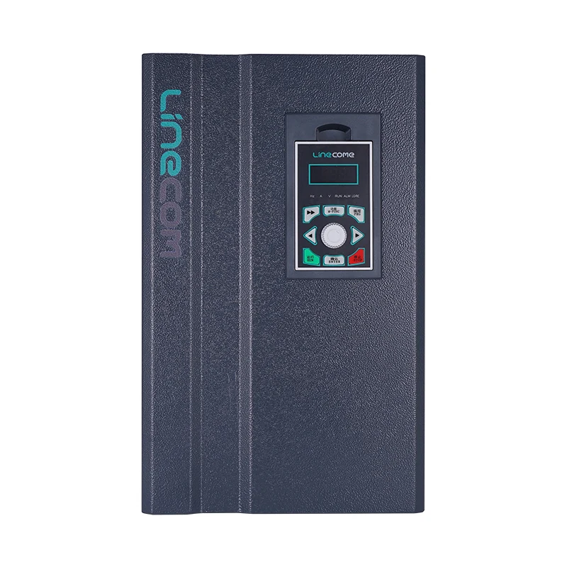
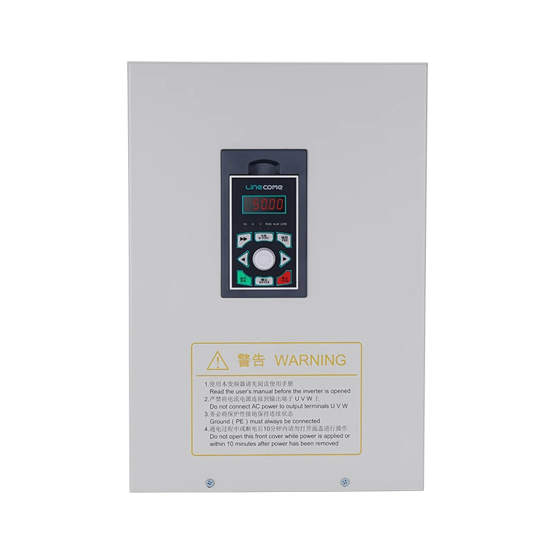
The LNC860S vector VFD is a relevant starting point for a motor-control enquiry. Its product photograph identifies the equipment family; it does not establish the cable accessory, terminal torque, EMC category or permitted installation arrangement for a particular order. These details belong in the approved equipment documents.
If the system architecture is unfamiliar, first review what an industrial VFD does. Keep supply-side earthing, motor-output cabling and control-signal wiring separate on the drawing. Their functions meet within the installation, but the inspection questions are different.
Why a shield needs more than a continuity reading
A motor drive switches its output electronically. The resulting electrical disturbance contains components far above the motor’s mechanical operating frequency. At those frequencies, the shape and length of a connection matter as well as its resistance measured with a handheld meter. A long, thin tail can show continuity and still make a poor high-frequency connection.
The RealPars explanation of electrical grounding introduces the different meanings of a ground reference and a current return. For a motor-cable shield, use the drive and cable instructions to specify the high-frequency interface. An approved clamp or gland can contact a broad area of the shield; the accessory preparation instructions establish the actual installation method.
Treat the return path as a chain. A correctly fitted cabinet gland cannot compensate for a shield left floating at a junction box. Likewise, an excellent motor-end termination cannot repair a cabinet entry plate that has no suitable bond to the enclosure. Inspection should follow the cable physically, rather than stopping at the first visible earth terminal.
Distinguish protective earth from EMC bonding
Protective earth provides a fault-protection function under the applicable electrical rules. The cable shield primarily addresses electromagnetic behavior unless the complete design explicitly approves it for an additional protective-conductor role. Do not assume a metallic covering is sufficient protective earth merely because it is connected at both ends.
Document the protective conductor separately, including its terminals, identification and required verification. The shield arrangement should then be inspected against the EMC design. A successful insulation or protective-conductor test does not demonstrate emissions compliance, and the absence of visible interference does not demonstrate adequate fault protection.
All alterations require competent personnel and safe isolation. Follow the drive instructions for stored energy and verification before touching terminals. The HSE guidance on working with electrical equipment provides the safety framework; this article does not prescribe a universal discharge waiting time or live measurement procedure.
Inspect both ends and every intermediate enclosure
At the cabinet, check that the selected gland or clamp suits the cable diameter and shield construction. Verify the contact surface, mounting method and mechanical support against the accessory instructions. Paint, contamination, loose hardware or an incorrect entry plate can undermine an otherwise suitable component. Do not scrape surfaces or modify corrosion protection without an approved bonding method.
At the motor, check the gland, terminal enclosure and connection to the motor frame. The exposed section of phase conductors should follow the motor and drive instructions. Keep the photograph focused on the actual termination after safe isolation; an exterior photograph of the motor gives little evidence about shield preparation inside the gland.
Intermediate devices deserve their own inspection record. A local isolator or junction box may interrupt the metallic path even though the phase conductors continue normally. Ask how shielding passes through that interface and whether the enclosure, glands and bonding arrangement were selected together. Do not operate an output-side isolator while the drive is running unless the approved design explicitly provides for that operation.
Use a termination checklist rather than a generic wiring rule
The checklist below combines the distinction between grounding functions and a route-based installation review with the equipment documentation. It contains no universal cable length, torque or resistance limit. Those acceptance values must come from the approved design and the actual accessories.
| Inspection point | Evidence to collect | Question before acceptance |
|---|---|---|
| Cable construction | Exact cable reference and preparation instruction | Does the termination accessory match every relevant shield layer? |
| Cabinet entry | Clear photograph and accessory reference | Is broad shield contact made to the intended bonded surface? |
| Drive connection | Equipment drawing and installed conductor identification | Are output conductors, protective earth and shield roles distinguished? |
| Junction or isolator | Enclosure drawing and both cable entries | Is the intended shield path maintained across the interface? |
| Motor entry | Gland reference and frame-bonding inspection | Does the arrangement match the motor and cable instructions? |
| Final installation | Route record and agreed functional checks | Does the complete system meet its documented acceptance criteria? |
A useful record identifies the person who checked each point, the document revision and any unresolved deviation. A tick without a drawing reference can hide a different interpretation between the panel builder and site installer.
Investigate interference without defeating protection
Begin with a symptom log. Record when the disturbance occurs, which loads are operating, the drive speed and the affected instrument or communication link. A problem that appears only when a particular machine starts deserves a different investigation from a fault that persists with the drive disabled. Correlation guides the investigation; it does not establish the coupling path by itself.
Then compare the installed route with the design. Look for recently added junctions, replacement glands, damaged cable coverings and mixed power-and-signal routing. Check whether a maintenance change has altered a bond that was present during commissioning. Correct documented installation defects before experimenting with settings.
If the symptom concerns an analog measurement, use the separate PLC analog input noise guide to investigate the receiving circuit. Do not assume that adding a capacitor or changing an analog shield will fix a defective motor-cable termination. Equally, do not attribute every signal fault to the drive: supply stability, sensor condition and scaling still require review.
Keep shielding and reflected-wave protection separate
Good shielding does not automatically solve motor terminal overvoltage, bearing-current damage or every cable-related problem. These effects depend on the equipment and installation. A filter selected for one purpose may not address another, and fitting an accessory changes the system that must be checked.
For the cable-length and motor-insulation discussion, consult VFD long motor cable assessment. The procurement package should state the installed route and any proposed output filter. Avoid a blanket claim that a particular shield construction permits unlimited cable length or guarantees trouble-free operation.
After a correction, repeat an agreed functional test under representative operating conditions. Preserve the original symptom record and compare it with the result. If the interference has disappeared, record the conditions tested and any remaining limits. Do not relabel that observation as a formal EMC compliance test unless the required test method and scope were actually completed.
Build a useful supplier and installer handoff
Ask for a marked cable-route drawing showing every enclosure and termination. Include the cable reference, accessory references, protective-earth arrangement, motor terminal requirements and responsibilities at the panel-to-site boundary. If the panel builder supplies only the cabinet, identify who approves the field cable and the motor-end termination.
Request photographs at the points that become concealed after assembly. The purpose is to make the inspection repeatable, not to collect attractive marketing images. Record deviations while access is available and agree the corrective action before energization. Where the route changes on site, revise the drawing instead of relying on an email description that the next technician cannot find.
The acceptance package should also state which checks establish electrical safety, which demonstrate the control functions and which address EMC performance. This prevents one successful test from being used to close several unrelated requirements. A motor that rotates correctly may still have an incomplete shield path or a missing protective conductor.
Learn the grounding principle before reviewing a cabinet
The following educational video supports the distinction between electrical reference connections and current return paths. It is background learning, not an installation instruction for the illustrated LINECOME equipment. Use the approved drive, cable and motor documents for the final arrangement.
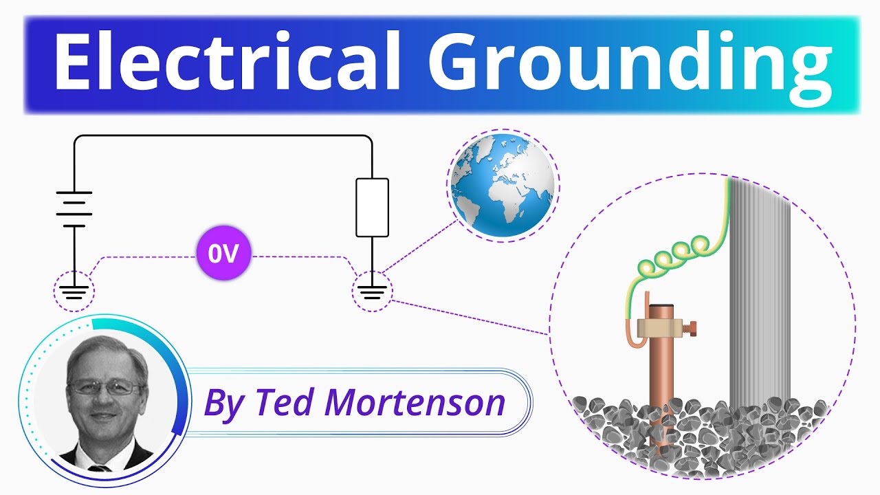
Video by RealPars. Watch Electrical Grounding Explained | Basic Concepts on YouTube.
Frequently asked questions
Should a VFD motor cable shield be grounded at both ends?
The normal EMC arrangement bonds the motor power-cable shield at both ends, using the termination method required by the equipment and cable manufacturers. Inspect intermediate enclosures too. Signal-cable practices cannot be transferred automatically to the motor power cable.
Does a shield replace the protective earth conductor?
Only where the complete design and applicable rules explicitly permit that protective function. Otherwise provide the specified protective conductor and treat shielding as an additional EMC requirement. Never remove protective earth as a noise experiment.
Is a continuity test enough to accept a shield termination?
No. Continuity is useful but does not establish high-frequency performance. Inspect the contact geometry, cable preparation, accessory compatibility and complete route, then perform the agreed system checks. Formal EMC claims require evidence appropriate to their scope.


