




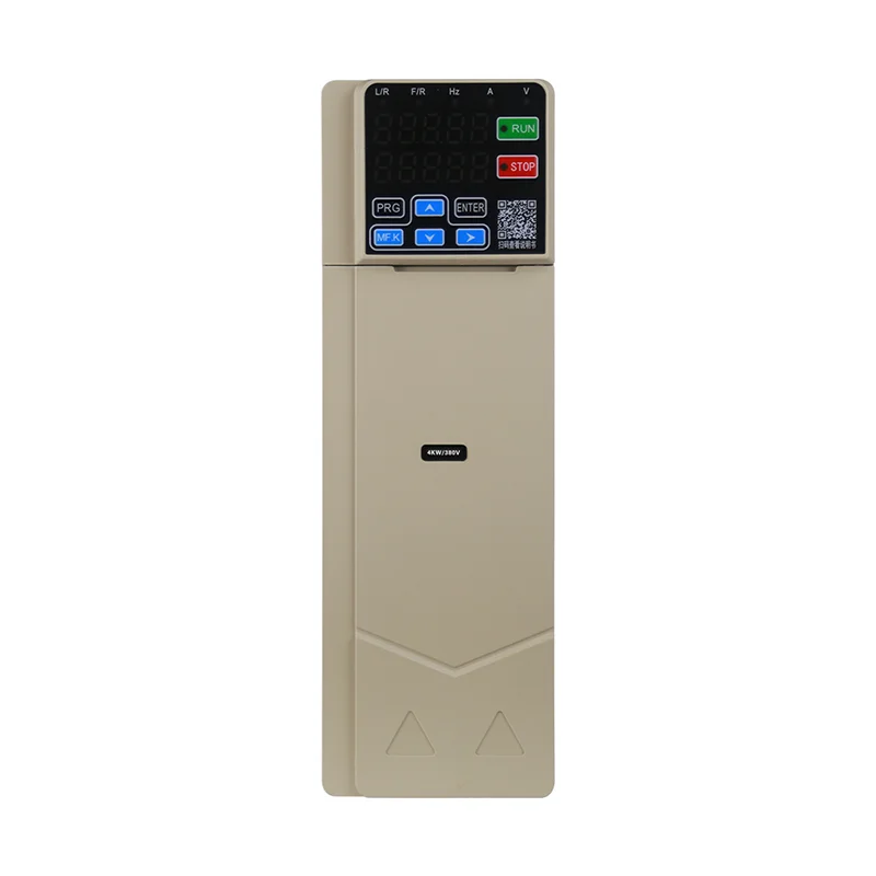
How frequency converter works at the motor terminals is the buyer-visible outcome: Motor terminal frequency and VFD output frequency change when the drive updates the fundamental frequency and coordinated voltage program the windings see, so speed and torque follow the process, not because utility Hz magically changed on the plant bus. Electronic frequency converters (packaged as VFDs on motor branches) still use internal power electronics, but this page stays on what changes downstream and what to verify on submittals, not a duplicate rectifier tutorial.
Power-stage block depth-rectifier, DC link, inverter naming under the phrase frequency converter how it works-lives on the Post 3013 sibling frequency converter how it works. Control physics and flux behavior live on how VFD works; static naming on basic principle of static frequency converter; icon reading on AC to AC frequency converter circuit.
Teams tracing frequency converter motor terminals behavior should still start here. Use the Variable Frequency Drive hub when you move from motor-side understanding to series selection.
 .
Motor terminals first: frequency, voltage boost, and speed outcome
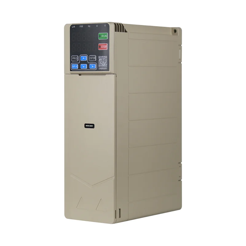
When a frequency converter works as intended, the motor sees a commanded output frequency within the drive’s published envelope, often paired with a V/F or vector control mode that adjusts voltage with frequency. Adjustable-speed drive summaries describe this as matching motor speed to process demand while the line-side feed may remain at 50 Hz or 60 Hz utility frequency.
Buyers care because nameplate rpm ties to synchronous speed at rated frequency; lowering commanded Hz slows the load without adding a mechanical gearbox step for every recipe change. That outcome-not internal PWM switch timing-is the first acceptance test on site.
 .
How this page differs from frequency-converter-how-it-works and VFD depth posts
This URL owns the grammar how frequency converter works (article a + verb order) with a motor-side and RFQ lens. The sibling frequency converter how it works owns the exact phrase frequency converter how it works with rectifier–link–inverter stage walkthrough-cross-read it when buyers ask “what are the three blocks?”
| Question shape | Primary vfdelec.com owner | This page gives |
|---|---|---|
| frequency converter how it works (stage names) | frequency converter how it works | Terminal outcomes + checkpoints only |
| how frequency converter works (this query) | This URL | Answer-first motor-side guide |
| Flux, control modes, physics | how VFD works | Links only |
| Static vs rotary naming | basic principle of static frequency converter | Not repeated |
| Block icons on PDFs | AC to AC frequency converter circuit | Not repeated |
No H2 titles or FAQ answers here copy the sibling power-stage page sentence-for-sentence.
The buyer-visible chain from plant feed to controlled shaft speed
Think in three observable steps on the motor branch-without opening a DIY schematic:
- Line-side feed stays at plant utility class (50/60 Hz on typical industrial drives) while the drive draws power through its input stage.
- Internal conversion reshapes energy on a DC bus and synthesizes variable AC-details on the sibling power-stage article.
- Motor terminals receive the programmed output frequency and voltage program; shaft speed responds for loads within the torque/speed capability of the motor and drive row.
Community talk on adjustable-speed drives repeats a practical commissioning point: if terminal frequency does not change when commanded, the problem is parameters, enable interlocks, or load-not “missing utility Hz conversion.”
Tip: A wide 0–500 Hz programmed output span on a catalog row describes motor-side programming envelope-it is not proof of exotic input frequency tolerance unless the input frequency class row says so.
.
Control references buyers actually program and audit
Field teams interact with frequency reference, acceleration/deceleration times, current limits, and mode selection (V/F vs sensorless vector where listed)-not individual IGBT switching events. Variable-frequency drive product pages list these as commissioning interfaces; buyers should demand they appear on submittals for the exact model quoted.
Harmonic and EMC planning remain facility engineering tasks; motor-side understanding does not remove the need for correct cable routing, grounding, and neighbor load coordination on the same transformer.
| Commissioning item | What “works” looks like on site | Common RFQ gap |
|---|---|---|
| Output frequency command | Motor accelerates to ordered Hz | Quote lists kW only |
| Accel/decel ramps | Smooth torque during changes | Missing time parameters |
| Current limit | Caps starting stress | Assumed “drive handles it” |
| Control mode | V/F or SVC as listed | Mode not specified |
| Fieldbus | Modbus RS485 where published | Protocol mismatch |
RFQ checkpoints before approving a frequency converter submittal
Use this checklist after you accept that how frequency converter works for your motor means adjustable terminal frequency-not utility Hz matching alone:
| Checkpoint | Pass criterion | Fail signal |
|---|---|---|
| Motor nameplate | Voltage class and Hz rating known | “Converter fixes everything” |
| Input frequency class on drive row | Matches plant (50/60Hz on published LNC tables) | Assumed from output span only |
| Output frequency span | Covers required speed range | Process needs field not listed |
| Control mode | V/F / SVC listed for quoted model | Missing mode on submittal |
| Enclosure and duty | Matches environment | Indoor catalog in washdown area |
| Utility Hz import jobs | Separate Hz-pair articles | Only this motor-side page |
When the job is strictly 50 Hz versus 60 Hz utility mismatch on imported equipment, follow Hz-pair guides linked from the hub-not motor-side programming alone.
 .
When motor-side frequency control does not solve the stated job
Frequency converters excel at speed matching on the motor branch; they do not automatically replace:
- Utility Hz conversion projects where the line itself must change class-see hub-linked Hz-pair articles.
- 400 Hz upstream bus to 60 Hz load stories requiring input-class proof beyond standard 50/60Hz rows.
- Fixed-speed-only duty where a soft starter’s ramp is enough-see Soft Starter hub material.
Recognizing those boundaries early prevents buying a drive when the RFQ actually needed a specialty input converter or a reduced-voltage starter.
Myth: frequency conversion “works like a transformer” on the wire
Procurement language sometimes imagines the converter as a passive transformer that remaps utility Hz on the conductors. Motor-branch drives instead synthesize output waveforms at the terminals while the plant feed remains at utility frequency class on the input side-rotary and transformer frequency changers are different equipment classes for different bus problems.
If stakeholders still demand block-diagram vocabulary, send them to frequency converter how it works for stage names while this page keeps motor-side acceptance language.
LNC610 and LNC820 product fit when motor-side control is the goal
Recommend LNC610 or LNC820 when published vfdelec.com tables show 50/60Hz input class, 0–500 Hz output span, and control modes that match the process, and motor nameplate data fits the chosen kW row.
The public LNC610 general-purpose VFD series page documents 50/60Hz input on its specification table with 0–500 Hz output, V/F control, SVC vector control, and Modbus RS485 on the overview-style listing. The public LNC820 general-purpose VFD series page lists 0–500 Hz output and the same control themes for broader kW bands.
Do not claim 400 Hz input tolerance from output span alone; input class must appear on the live row for the exact model quoted.
| Public listing theme | Buyer use after this page | Verify on site |
|---|---|---|
| 50/60Hz input class | Standard utility-fed motor branches | Line measurement |
| 0–500 Hz output span | Speed programming envelope | Process min/max speed |
| V/F and SVC | Mode selection on submittal | Motor data sheet |
| Modbus RS485 | Supervisory interface where shown | Network plan |
 .
Frequently asked questions
Short answers mirror residual buyer questions; power-stage depth stays on frequency converter how it works.
How frequency converter works for a pump operator on the floor?
The motor runs at the speed matching the programmed output frequency-you hear and measure speed change, not utility Hz drift on the grid.
Is this the same article as frequency converter how it works?
No-this page uses different H2s and focuses on motor terminals and RFQ checks; the sibling owns rectifier–link–inverter stage depth.
What should I see at the motor terminals when it works correctly?
Stable acceleration to commanded frequency within published drive limits, with no stall unless load exceeds torque capability.
Does 0–500 Hz output prove the drive accepts 400 Hz input?
No-input frequency class must be read on the published input row; output span alone is insufficient.
Where do V/F and vector control get explained in depth?
See how VFD works for control physics beyond this motor-side summary.
Can I commission from this page without a submittal?
No-use the RFQ checkpoint table and vendor documents for the exact model.
When is a soft starter enough instead?
When you only need reduced inrush at fixed line frequency-see soft starter hub articles, not a frequency converter.
When do LNC610 or LNC820 fit?
When input class is 50/60Hz on the public page and motor data matches the kW row – confirm on live product pages before purchase.


