




A star delta transition current spike should be investigated against the exact switching sequence before anyone changes the timer or raises a protection setting. First establish whether the event occurs during acceleration in star, during the open interval, at delta closure or after the motor begins running in delta. Then compare current, supply voltage, motor speed and contactor operation on the same timeline. The cause may involve insufficient acceleration, incorrect connections, unsuitable changeover timing or a mechanical load that star starting cannot accelerate adequately. This guide organizes the evidence needed to distinguish those cases and decide whether adjustment, repair or a different starting method is justified.
Locate the event before choosing a remedy
“Trips on starting” is too broad to be a useful fault description. Ask the operator to identify whether the motor begins moving, how it sounds before changeover, which contactors operate and which protective device reports the fault. Save the actual trip code or indication rather than translating every event into “overload.” A short-circuit protective operation and an overload trip require different investigations.
A conventional open-transition star-delta starter has a star acceleration interval, a break-before-make transition and delta running. A current pulse when delta closes is not automatically proof of a wiring short circuit, but neither should it be dismissed as normal without comparison with the equipment limits and expected sequence. Use approved instrumentation capable of capturing the event; a slowly updating panel ammeter may miss a brief peak.
The Engineering Mindset explanation of star-delta operation provides the underlying connection sequence. For the broader LINECOME explanation, see how a star-delta starter works. This article concentrates on a failed transition and the records needed to diagnose it, rather than repeating a general operating description.
Confirm that the motor is suitable for the supply and starter
Before analyzing timing, verify the motor nameplate, winding diagram, supply and six accessible winding terminals. The motor must be suitable for delta running at the actual supply voltage. Having six leads does not by itself prove that the chosen connection is correct. Have qualified personnel reconcile the terminal identification and approved circuit drawing with the physical motor connections under safe isolation.
Reduced-voltage starting also reduces the available accelerating torque. A motor can turn in star yet fail to reach a suitable speed with the connected load. Extending a timer cannot create torque that the motor does not have in that starting condition. Examine whether a compressor unloader, valve position or other load-relieving arrangement is working as designed. Confirm the actual process state rather than assuming that the machine is unloaded because the control screen says so.
The LNC-QX4 star-delta starter cabinet is a relevant LINECOME product family for this type of enquiry. Select the delivered configuration from the motor and application data. Catalogue examples or approximate timings should not be treated as the accepted setting for a different motor, supply or load.
Keep three different timing questions separate
The star acceleration duration determines how long reduced-voltage acceleration is available. The open transition interval separates star opening from delta closure. Mechanical contactor opening and closing times determine what the power contacts actually do. A timer’s displayed value does not establish all three.
If star duration is insufficient for the application, delta may connect while the motor still needs substantial acceleration. If the open interval is excessive, the motor may lose speed before reconnection. If the interval or interlocking is inadequate, an unsafe overlap can occur. These possibilities require examination of the approved contactor and timer arrangement; there is no universal delay value that is safe for every cabinet.
Do not remove electrical or mechanical interlocks to make a troublesome sequence run. If contactor operation is inconsistent, investigate coil supply, wiring, contact condition and the specified components. Use control indications as supporting evidence, but recognize that an auxiliary contact or PLC bit may not reproduce the exact instant of power-contact movement.
Prepare a synchronized capture plan
Agree the capture method with a qualified electrical engineer and the machine owner. Identify which conductor currents are being recorded, where voltage is measured and how the contactor state and motor speed will be correlated. Select instrument ratings and access methods for the installation. Where possible, establish measurements with the equipment isolated and use approved remote recording arrangements.
Before repeat testing, save the current settings, drawings, fault history and motor data. Set the permitted number of attempts and cooling conditions using the motor and starter instructions. Repeated unsuccessful starts can heat the motor and contactors even when each attempt appears short. Stop the sequence if there is abnormal noise, evidence of contactor overlap or a suspected connection fault.
The CCOHS lockout/tagout guidance explains why operating controls do not replace energy isolation. The investigation plan must address the site’s actual electrical and mechanical energy sources and the applicable local requirements. Live diagnosis, where justified, needs its own qualified work method; this checklist is not a live probing procedure.
| Observed timing of the event | Evidence to capture | Investigation to prioritize |
|---|---|---|
| High current continues throughout star | Current trend, speed and actual load state | Acceleration capability, supply and mechanical load |
| Sharp event at delta closure | All phase currents, voltage and switching timeline | Motor lead mapping, transition interval and speed before reconnection |
| Contactor chatter or repeated operations | Coil supply, command history and contactor observations | Control supply, loose connections and component condition |
| Fault follows sustained delta running | Running current balance and process load | Motor loading, phase condition and overload protection |
| Behaviour changes between identical starts | Hot/cold state, supply and mechanical conditions | Intermittent contactor, supply or process variation |
This is a qualitative diagnostic table, not a table of permissible current peaks. Acceptance limits must come from the actual equipment, protection study and project specification.
Interpret the acceleration interval
A useful trace shows how current and speed evolve before transition. If speed is still increasing substantially when star is removed, determine whether the approved star duration was sufficient. If speed levels off well below the required condition, determine why the available motor torque and load torque have reached a balance. These are different findings and should not receive the same automatic timer adjustment.
Check the supply during acceleration rather than only before the start. A weak supply or a substantial voltage reduction can affect available torque and contactor operation. Compare results with the machine’s normal and worst permitted loading conditions. A cabinet that starts a disconnected motor has not demonstrated that it can start the intended process.
Where an unloaded start is specified, verify the unloading function and its feedback. For a compressor, for example, a process fault can turn an expected light start into a loaded one. Record the process condition with the electrical trace so the electrical team does not spend hours compensating for an unrelated mechanical problem.
Investigate delta closure without masking the fault
Under safe isolation, verify winding identification, connections and the contactor circuit against approved drawings. Inspect the equipment for loose or damaged connections, worn contacts and incorrect replacement components. Confirm that any recent motor rewinding or terminal-box work has been reflected in the records. A fault appearing after maintenance deserves a comparison with the last known working configuration.
Then review the verified switching sequence. Differentiate the commanded sequence from actual operation, and preserve the evidence supporting the chosen transition interval. If the motor’s residual electromagnetic state and the reconnection condition require specialist assessment, provide the captured waveforms to the motor and starter suppliers rather than guessing at a corrective setting.
Never use a larger fuse, higher instantaneous threshold or disabled overload function as a diagnostic shortcut. A setting may be wrong, but the correction needs coordination with the conductor, contactor, motor and panel ratings. The separate motor control panel breaker coordination checklist explains the documents to request before protection changes are accepted.
Decide when another starting method is the better answer
If a verified motor and healthy cabinet cannot accelerate the real load acceptably in star, reconsider the starting method. A soft starter can change how starting voltage and torque are applied, while a suitable variable-frequency drive changes the motor supply frequency as well as voltage. Neither option should be selected solely because it removes a contactor transition.
Compare load torque, required starting current, supply limits, starting frequency and whether variable operating speed is actually needed. Check enclosure heat, bypass arrangements, motor protection and application-specific stopping requirements. A retrofit quotation should state what existing equipment remains and what must be replaced or revalidated.
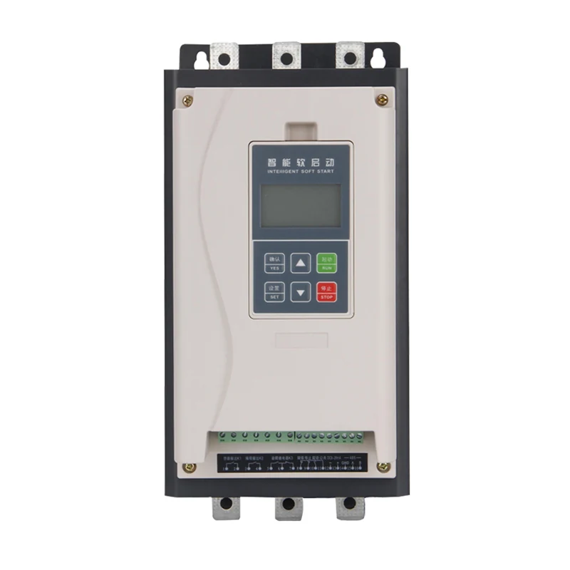
For a broader comparison before selecting a replacement, review advantages and disadvantages of star-delta starters. The illustrated alternative soft starter is a separate product, not an internal component of the QX4 cabinet or evidence of a completed conversion.
Turn the repair into a repeatable acceptance test
After correcting a confirmed cause, repeat the agreed start under the relevant load conditions. Compare the new trace with the original, including current, voltage, switching events and speed. Confirm that the improvement did not merely move the problem into a longer acceleration interval or an unacceptable thermal duty. Verify the protective functions remain active and correctly documented.
Include hot and cold conditions where required by the project. Record the actual settings, contactor and timer identities, any replacement parts and the accepted cooling interval. If operating conditions differ from those available during the test, list that limitation explicitly rather than granting unconditional acceptance.
The handover should identify the diagnosed cause, evidence, corrective work and final test result. Keep an accessible settings backup and a clear instruction for what operators should record if the fault returns. That creates a usable maintenance baseline rather than a note saying only “timer adjusted.”
Further learning on the switching sequence
The Engineering Mindset video below explains the star and delta connections and contactor sequence. Use it to understand which events belong on the diagnostic timeline. It does not establish the permissible delay or protection setting for your equipment, and its illustrative wiring should not replace the approved project drawings.
Video by The Engineering Mindset. Watch Star Delta Starter Explained – Working Principle on YouTube.
Frequently asked questions
Should I always increase the star timer after a transition trip?
No. First determine whether acceleration is continuing, has stalled at a low speed or is already satisfactory. Wiring, contactor operation and the open transition interval can cause problems that a longer star duration will not fix.
Is the panel ammeter enough to measure a transition spike?
It may not capture a brief event. Use appropriately rated recording equipment and a planned method that correlates current with contactor operation and motor speed. Have qualified personnel select and install the measurement arrangement.
Can a larger breaker solve the problem?
Do not increase protection to hide an unexplained event. Confirm the cause and review the complete motor branch and panel coordination before accepting any protective-device or setting change.


