




VFD 4–20 mA signal troubleshooting starts by separating the electrical current loop from the drive’s interpretation of that signal and the control logic selecting the speed reference. A healthy transmitter can feed an incorrectly scaled input; a correctly scaled input can be ignored because another reference source is active. Compare the transmitter indication, measured loop current, drive input monitor and active reference before changing PID gains or replacing hardware. Establish a safe process state before any signal injection, because a test current may command motor movement or alter pump pressure.
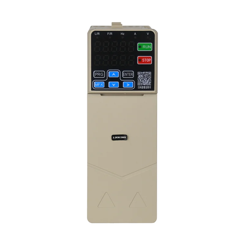
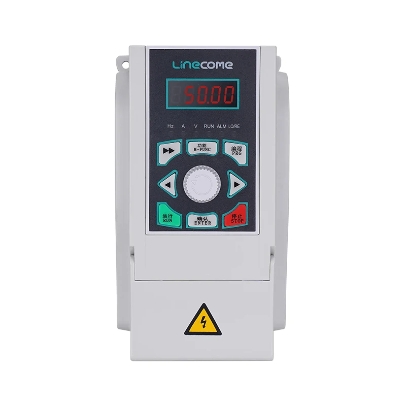
This guide addresses conventional industrial analog loops where the selected drive and interface support the required current input. It does not establish terminal assignments for every LINECOME model. Use the LNC610 general-purpose VFD product page for catalog context and obtain the exact order-specific wiring diagram and manual. For the underlying power conversion, see how a variable frequency drive works.
Draw the signal path before measuring
Identify what the current represents. It may be a direct speed demand from a PLC, a pressure measurement entering a drive’s PID controller, or a status signal traveling from the drive to another system. Those are different paths. A technician measuring an analog output may be observing actual speed while the fault concerns an input demand. Mark signal direction and variable meaning on the loop drawing.
Record the transmitter or PLC output type, power source, receiving input, isolators, barriers and intermediate terminals. Identify active versus passive interfaces from their manuals. Do not assume that two terminals labeled plus and minus imply a complete compatible loop. Connecting two powered outputs together or adding a supply to an already powered interface can damage equipment.
The NI current-loop fundamentals guide explains the series-loop principle and the need to account for voltage drops. Apply those principles using the specifications of the actual devices. A drawing that omits an isolator or receiver load can conceal the reason a signal stops increasing near the upper end of its range.
Establish a safe test boundary
Agree what the process may do during the test. A pump can start when an interlock returns, even if the person injecting a signal believes the test concerns display scaling only. Coordinate with operations, identify remote start commands and define the response to a lost signal. Keep independent protective functions available throughout the approved test arrangement.
Use qualified personnel, suitable instruments and the site’s electrical work procedure. The official electrical safety work-practice text covers isolation and verification responsibilities. A low-voltage signal terminal can sit beside hazardous power terminals, so the signal voltage alone does not define the exposure. Rewiring normally requires isolation; any necessary energized diagnostics need a separately approved method.
Do not connect a meter in current mode across a voltage supply. Confirm instrument mode, lead positions and the intended connection before testing. A suitable milliamp clamp can sometimes obtain loop-current evidence without opening the loop, but its resolution and access must suit the measurement. If series measurement is needed, follow the approved isolation and reconnection sequence rather than opening an operating loop casually.
Compare four observations at the same time
Record the process variable or controller demand, current reaching the receiver, the drive’s analog-input monitor and the active speed reference. Time alignment matters. A pressure reading taken before a demand change cannot be compared reliably with a drive value taken after the controller has reacted. Capture stable test points and any transition associated with the complaint.
Start with a condition the process team understands. If a PLC output is supposed to hold a defined demand, obtain its configured engineering range and raw output value. If a transmitter represents pressure, compare its local reading with an independent suitable process reference where available. Electrical testing can establish that a current was transmitted accurately without proving the original pressure measurement is correct.
When the input monitor agrees with the current but the active reference does not, focus on control selection, scaling or limits. When the current is wrong before reaching the drive, investigate the upstream loop. This division prevents a good VFD from being replaced for a transmitter, supply or drawing error.
Use scaling calculations to identify interpretation errors
For a linear signal with 4 mA representing the lower engineering value and 20 mA representing the upper value, the normalized fraction is (I − 4 mA) / 16 mA. The engineering value is lower value + fraction × (upper value − lower value). These are linear interpolation equations, not a universal instruction to program a drive for any particular process.
For example, assume an explicitly configured 0–10 bar pressure transmitter with a linear 4–20 mA output. At 12 mA the fraction is 0.5, so the corresponding pressure is 5 bar. At 8 mA it is 0.25, corresponding to 2.5 bar. If the receiving device interprets 12 mA as 7.5 bar, compare the configured endpoints and input mode before adjusting the sensor.
Use units throughout the worksheet. Check whether a displayed percentage refers to the full electrical input range, the configured engineering span or the final speed reference. A pressure input may be converted into a PID demand and constrained by operating limits; it should not be expected to equal motor frequency directly. For controller behavior after the measurement path is verified, use our constant-pressure pump PID guide.
Do not extrapolate the interpolation equation into fault handling. Below-range and above-range currents may represent configured alarms, an open circuit or other conditions. The device manuals and project specification define those meanings. Confirm whether fault signaling is enabled and what action the drive takes when it detects the condition.
Diagnose by the boundary where evidence diverges
The table below is a qualitative diagnostic worksheet. It follows the loop and configuration principles explained by NI and Fluke’s physical-layer control troubleshooting guide. It does not assign fault codes or default thresholds to LINECOME products.
| Observation | Boundary to investigate | Useful evidence | Avoid this shortcut |
|---|---|---|---|
| Current absent at receiver | Supply, continuity, output enable and loop architecture | Actual supply voltage and approved wiring checks | Assuming the VFD input has failed |
| Current plateaus before full scale | Available loop voltage and total burden | Device voltage requirements and upper-range measurements | Increasing supply beyond device limits |
| Current correct, input monitor wrong | Current/voltage mode and input configuration | Exact input assignment and scaling readback | Applying PID tuning to an electrical mismatch |
| Input monitor correct, speed demand wrong | Reference arbitration and operating limits | Active source, local/remote state and selected limits | Assuming the analog input always owns speed |
| Stable stopped, unstable while running | Routing, bonding, interference and supply behavior | Synchronized signal and motor-state records | Adding arbitrary capacitors or earth connections |
Prove the receiving path with controlled test points
When the process is secured and the test method approved, a suitable calibrator can help distinguish the receiving path from the field transmitter. Verify whether the selected instrument must source current or simulate a loop-powered device. That choice depends on the circuit’s existing supply arrangement. Record the original connections and restore them after the test.
Apply agreed low, middle and high points within the intended range, and record both the injected current and receiving indication. The purpose is to identify offset, span or nonlinearity; it is not permission to command maximum motor speed. Some projects can validate the indication path while motion is positively prevented. Others need a separately engineered functional test under controlled operating conditions.
If the receiver reads correctly during local injection but fails with the field loop restored, extend the investigation upstream. Test one boundary at a time so the result has a clear meaning. Replacing a transmitter, adding an isolator and changing parameters simultaneously may make the symptom disappear while leaving the cause unknown.
Investigate interference without random wiring changes
A signal that changes when the motor runs deserves a synchronized record of current, supply voltage and operating state. Inspect the installed cable route against the approved design and manufacturer instructions. Shared routes, damaged shields, loose terminals or unsuitable reference arrangements are prompts for investigation, not diagnoses that can be established from a photograph alone.
Protective bonding and signal reference have different functions. Do not disconnect protective earth to quiet a noisy measurement. Do not add a common connection merely because it helped another machine with a different input architecture. Review isolation requirements and allowed common-mode conditions before selecting a signal conditioner or changing the grounding arrangement.
The VFD installation guide gives the broader mounting and wiring context. For the particular fault, keep an evidence trail showing which change was made, why it was justified and what measurement improved. Filtering can reduce displayed fluctuations, but it can also hide a real process change or delay a protective response; assess that tradeoff explicitly.
Return the system to its intended control mode
Remove test forcing, reconnect field devices, restore approved parameter values and confirm the selected reference source. Verify remote and local behavior with operations. Test the agreed lost-signal response using a controlled method, without defeating an independent safety system. Confirm that alarm acknowledgement does not unintentionally restart the equipment.
The handover should include the loop drawing revision, instrument identification, engineering endpoints, as-found values, corrective action and as-left test results. For a LINECOME enquiry, provide the exact drive designation, control-board or firmware information when available, input type, transmitter or PLC interface and the symptom timeline. Product photographs do not establish an input’s current range, terminal numbers or isolation characteristics.
Further learning: analog input and output acceptance
RealPars demonstrates analog I/O acceptance testing in the lesson below. It helps explain controlled test points and indication checks. Its example equipment does not define the terminals or parameter names on the installed VFD.
Video by RealPars. Watch Factory Acceptance Test Explained – Part 3 | PLC Analog IO Test on YouTube.
Frequently asked questions
Does 4 mA always mean zero motor speed?
No. It represents the configured lower endpoint of a signal. A drive may interpret that signal as pressure feedback, apply speed limits or select a different reference source. Check the complete configuration.
Can I test a VFD input by shorting its signal terminals?
Do not use an improvised short as a substitute for the approved test method. Determine the loop architecture and use a suitable instrument within the input and supply limits.
Why does the keypad show the correct input but the motor speed differs?
Check the active reference source, local or remote selection, PID operation, limits and interlocks. A correct input indication establishes only one stage of the control path.


