




When a soft starter bypass contactor is not closing, first establish whether the starter has completed acceleration and issued a valid bypass command. Then separate the coil circuit, mechanical movement, main power contacts and feedback signal. An audible click or an illuminated output does not prove a successful power transfer. Do not force the contactor closed or keep restarting to clear the symptom. The correct sequence depends on the actual starter, wiring arrangement and protection design. This guide provides an evidence-based fault investigation for qualified personnel, rather than a replacement for the equipment service manual.
Identify the bypass arrangement before diagnosing it
An external bypass contactor, an internal bypass assembly and an across-the-line emergency bypass are different arrangements. Obtain the power drawing, control drawing, starter manual and contactor identification. Mark the normal motor current path during acceleration and during steady running. Identify what provides motor overload protection in each state.
A bypass contactor connected across the starter’s power section normally changes the running current path after the permitted transfer condition. It is not automatically a backup starter, isolation device or safety stop. A drawing that simply labels a component “bypass” is insufficient to establish those functions. Confirm how faults, stop commands and loss of control supply are handled.
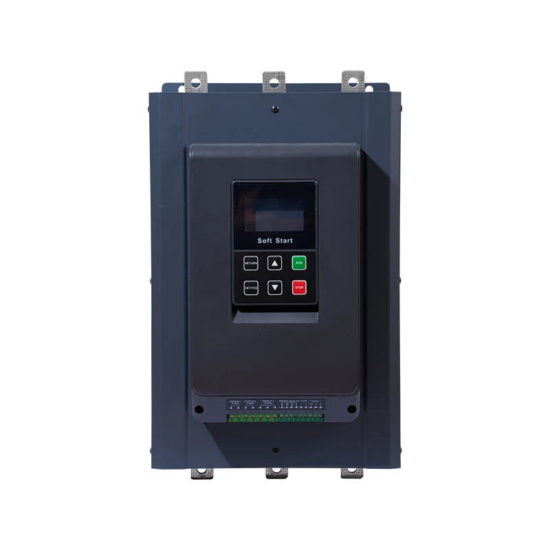
The PR800 external bypass soft starter is a relevant LINECOME product family for this topic. Its product page identifies an external bypass arrangement; the exact contactor, coil circuit, terminal assignments and settings still require project documents. Do not infer them from the product image or transfer another manufacturer’s fault code to this starter.
Separate an incomplete start from a failed transfer
Read the fault history and operating state before resetting. Record whether the motor accelerated, whether the starter reported end of ramp, whether a bypass command appeared and how long it took for the fault to occur. Pair those observations with the machine load and supply conditions. A motor that never reaches the required transfer condition may leave the bypass open correctly.
If acceleration remains incomplete, investigate that branch first. A jammed load, an unsuitable starting duty or a supply disturbance is not corrected by overriding the bypass command. The soft starter operating sequence provides the broader context. This article focuses on the later transfer boundary, where permission should produce a controlled contactor response.
Some products infer bypass health from electrical measurements, while others use external feedback or different internal logic. Manufacturer service documents therefore matter more than a generic alarm name. During research, bypass troubleshooting manuals show both “not closing” and “not opening” conditions; these are separate failures and should not be collapsed into one reset procedure.
Preserve a safe diagnostic boundary
Before physical inspection, stop the equipment, isolate all relevant energy sources, lock out according to the site procedure and verify the safe condition. Include separate control supplies and stored mechanical or process energy. A stopped motor or an open control contact does not establish isolation. Only authorized personnel should carry out any energized diagnostic activity under a suitable assessment and procedure.
HSE’s maintenance guidance emphasizes planned maintenance, isolation and controlling stored energy. Apply those principles to the complete machine, including the process being driven. Removing a cabinet cover to reach a coil can expose unrelated power equipment even when the motor command is off.
Save the original parameter set and drawing revision. Photograph identifiers rather than assuming that a fitted replacement matches the original bill of materials. Mark any temporary test connections in the work record, and give one person responsibility for verifying their removal before restoration.
Build a command-to-feedback timeline
Use the following worksheet to organize the evidence. These are diagnostic distinctions, not guaranteed causes. Acceptance limits, permissible test methods and timing must come from the actual equipment documentation.
| Observed state | Investigation boundary | Evidence needed before changing hardware |
|---|---|---|
| No transfer permission after starting | Starter state and acceleration completion | Fault history, motor behavior and actual end-of-ramp condition |
| Permission present, no output command | Configuration or sequence logic | Assigned output function, interlocks and current drawing |
| Output commanded, coil does not operate | Control supply and coil circuit | Coil identity, permitted measurement and conductor path |
| Mechanism moves, transfer not verified | Main poles and electrical transfer | Approved electrical checks and contact condition |
| Transfer occurs, indication stays open | Auxiliary feedback path | Contact function, terminal assignment and input state |
| Contactor closes, then drops out | Holding supply, command or machine permissive | Time-correlated output, feedback and event history |
Trace one transition at a time. An HMI symbol may represent a command, an auxiliary contact or a derived logic state. Label each trace by what it actually measures. If a maintenance report calls all three “bypass on,” the investigation can mistakenly replace a healthy contactor because the feedback wiring is wrong.
Examine the control circuit without forcing the contactor
Compare the installed coil rating and supply type with the drawing and approved replacement specification. AC and DC coils are not interchangeable merely because the printed voltage looks similar. Where an interface relay, suppression device or electronic coil module is used, identify it and follow its installation instructions.
With the circuit safely isolated, inspect terminals, connectors, conductor damage and evidence of overheating. Check whether a recent modification changed the output assignment or introduced an additional permissive. If energized evidence is necessary, the qualified technician must select a safe method and suitable instrument; this article does not prescribe exposed terminal probing.
A PLC output indicator proves neither adequate coil supply nor continuity through the complete circuit. Likewise, a normal supply measured at idle may not establish behavior during pickup. Record the relevant operating event, the measurement boundary and the test limitations rather than treating a single number as complete proof.
Do not bridge an interlock, push the contactor in by hand or connect the coil to an improvised supply to keep production running. These actions can bypass sequencing and protection, create an uncontrolled start or damage equipment. Escalate undocumented circuits to the responsible panel designer before testing further.
Distinguish main contacts from auxiliary feedback
A contactor’s auxiliary contact is used in control circuits and can indicate mechanism position, but its meaning depends on the fitted contact block and wiring. It does not independently prove that every main power pole carries current correctly. Conversely, an open feedback circuit can report a failed transfer even when the mechanism moves.
RealPars’ contactor explanation distinguishes coil, main contacts and auxiliary contacts. Use that distinction to label the schematic and test record. It does not establish a bypass-specific timing requirement or authorize substitution of a contact block in a safety-related circuit.
Inspect feedback wiring against terminal functions, including normally open versus normally closed logic and the expected de-energized state. Check whether the program input uses inversion, a delay or a fault latch. Record what happens during both pickup and release; a welded or sticking condition on stopping can be as significant as failure to close.
Check the protection path before return to service
If the bypass arrangement changes which components carry running current, confirm which devices continue to measure and protect the motor. Do not assume the starter’s electronic overload remains effective for every external connection. The responsible designer must verify the exact power path, sensor location and coordinated protection arrangement.
Compare the repaired system with the bypass contactor selection checklist. That article addresses specification and verification; this fault investigation should produce the evidence needed to use it. If an overload trip accompanied the transfer problem, preserve both events rather than simply increasing a protection setting to remove the alarm.
A replacement contactor requires more than matching current printed on the front. Provide the duty, utilization category required by the design, coil specification, auxiliary arrangement, mounting details and approved coordination information. Do not substitute an emergency direct-start function for normal bypass operation without a separate engineered design.
Run an agreed acceptance sequence
Before restoration, define success in observable terms: correct initial open state, permitted acceleration, controlled transfer, stable running, proper release on stop and the specified fault response. Establish the allowable start duty and cooling interval from the equipment documentation so that troubleshooting does not become repeated thermal stress.
Carry out a controlled test with the load condition and protective arrangements agreed by the responsible engineer. Record starter state, bypass command, feedback and fault status in the same timeline. Where power-path verification is required, use the manufacturer’s approved procedure. A successful unloaded demonstration may not reproduce a problem that occurs under normal production load.
Test stopping as carefully as starting. Confirm that temporary connections and software forces are absent, the command source is restored and the cabinet is closed before normal operation. Do not deliberately create a hazardous failure to demonstrate a trip; use approved simulations or test facilities where specified.
HSE’s PUWER overview describes the importance of maintained equipment, suitable controls and isolation. It is UK guidance, not a declaration of compliance for every destination market. The finished panel and machine still require assessment against their applicable rules and project requirements.
Send a service request that can be acted on
Provide the starter and contactor model identifiers, motor nameplate, power and control drawings, bypass arrangement and the event timeline. Include whether the problem began after maintenance, a supply incident or a software change. Attach the exact fault wording, rather than translating several alarms into “contactor faulty.”
State which checks were performed, by whom and under what load. Separate confirmed observations from suspected causes. If the command never appeared, say so; if the coil moved but feedback failed, say that instead. A concise boundary-based report helps the supplier request the correct next evidence and reduces unnecessary replacement of power components.
Retain the previous and final configuration, approved replacement details, updated drawings and acceptance record. Schedule a follow-up observation during representative production if the commissioning test could not cover the original conditions. The repair is evidenced by the full sequence and retained protection, rather than a temporary disappearance of the alarm.
Further learning: coil, power contacts and feedback
This RealPars educational video explains a contactor’s operating principle and the distinction between power and auxiliary contacts. It supports reading the schematic; use the actual soft starter manual for transfer logic and service procedures.
Video by RealPars. Watch What is a Contactor? | Working Principles on YouTube.
Frequently asked questions
Does a click prove that the bypass contactor is working?
No. A click indicates mechanical movement, but the main poles, control sequence and feedback still need the checks required by the equipment documentation. An auxiliary indication alone does not verify every power pole.
Can I close the bypass contactor manually to finish the start?
Do not force a transfer or defeat interlocks. The open contactor may reflect incomplete acceleration or a valid protective condition. Secure the equipment and investigate the command, coil circuit and feedback using the approved procedure.
Is the contactor faulty if the PLC reports no bypass feedback?
Not necessarily. A missing input can originate in the auxiliary contact, wiring, input configuration or logic. Compare the actual command, mechanism state and feedback path before replacing components.


