




Soft starter short circuit coordination is the verification of a specified starter and its protective combination under defined fault conditions. A motor current rating, a large circuit breaker or a successful factory start does not establish that result. Begin with the required coordination outcome, the supply voltage, the available fault current and the exact components in the circuit. Then obtain evidence that covers that combination. Keep the starter’s post-fault service requirements and the complete cabinet’s short-circuit rating visible in the same review, because they answer different procurement questions.
Define the question the purchase specification must answer
A useful specification identifies what must remain safe during a fault and what service condition is required afterward. It also identifies the rating and assessment method required for the installed assembly. Put those requirements into the inquiry before asking a supplier to choose a fuse or circuit breaker.
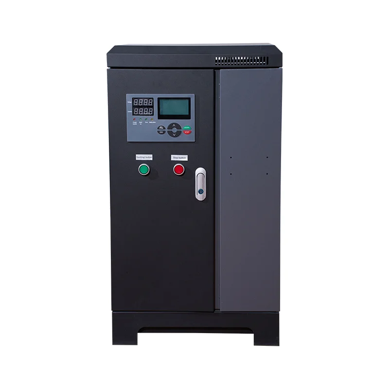
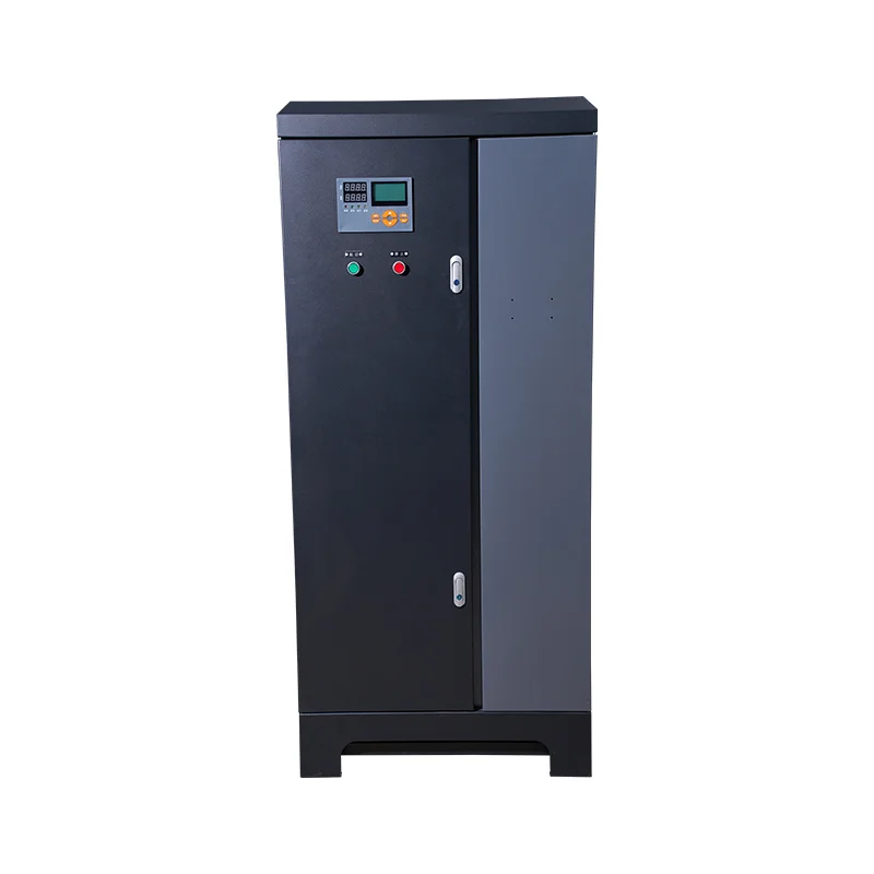
For a split-type LR800 soft starter cabinet, request the order-specific power diagram, bill of materials and supporting protection evidence. The catalog product identifies a cabinet family. Its motor-power range and external appearance do not establish a Type 2 combination, an assembly rating or the fault current available at the customer’s installation.
The soft-starting sequence guide explains the normal ramp and running stages. Coordination adds a different operating condition to that picture. It asks how the specified circuit responds to a short circuit, including the interaction of the protective device, switching components and semiconductor power stage. The evidence should describe the actual circuit arrangement being supplied.
Separate the ratings in the review
Motor overload protection addresses a motor’s thermal loading under its intended duty. Short-circuit protection addresses a different fault condition. A starter’s normal current capability and overload settings are therefore insufficient evidence for its short-circuit protective combination.
A circuit breaker’s interrupting rating describes its capability under stated conditions. The assembly’s short-circuit current rating considers the applicable components and permitted combinations using the relevant assessment method. Record each rating with its voltage and supporting conditions so a high number on one device does not get transferred to the entire cabinet.
UL Solutions’ combination motor-controller resource explains the use of specified component combinations and directs users to the relevant rating information. Its scope illustrates why the disconnecting means, protective device, controller and overload protection belong in a combined review. For a particular soft starter cabinet, obtain evidence applicable to that exact product and circuit.
Understand Type 1 and Type 2 service outcomes
In a coordination review, Type 1 generally allows the starter to require repair or component replacement after the specified short-circuit test, while maintaining the required safety outcome. Type 2 sets a more demanding continued-service outcome for the specified combination. The precise requirements, permitted contact condition and maintenance instructions depend on the applicable standard and tested arrangement.
The manufacturer’s coordination documentation must identify the standard, device combination, voltage and fault conditions. Semiconductor starter arrangements can have different protection requirements from an electromechanical starter. Ask explicitly which evidence covers the semiconductor power stage and which covers only contactors or other parts of the circuit.
Do not interpret Type 2 as permission to reset equipment immediately after a real fault. The fault must be located and cleared, equipment condition assessed, operated protective devices handled correctly and the manufacturer’s recovery procedure followed. A fuse can perform its intended protective function and require replacement even when the coordinated equipment has met its specified outcome.
For a project with a long interruption cost, discuss the expected recovery procedure during procurement. Identify replacement protective devices, inspection requirements, access arrangements and who can authorize return to service. That makes the selected service outcome useful to the maintenance team rather than leaving it as an unexplained label on a quotation.
Check evidence against the exact circuit
Start with a controlled copy of the coordination table or test-supported declaration. Record its issuer, revision and applicable standard. Confirm the starter reference, supply voltage, protective-device reference and maximum permitted rating or setting. Check all notes rather than relying on the table row alone.
Confirm the connection arrangement. An in-line circuit, an inside-delta circuit and a circuit with external bypass components may require different evidence. Match line contactors, bypass contactors and other specified components to the actual bill of materials. If a semiconductor fuse is required for the claimed outcome, its exact family and limits must be reflected in the supplied circuit.
Include the conditions that affect applicability, such as the declared fault-current level and any installation restrictions. A table written for another manufacturer’s starter can explain how to read coordination evidence, but cannot establish the LR800 combination. Require supporting information from the responsible equipment supplier for the proposed order.
The following table is a proposed document-review checklist. It contains no assumed ratings for the pictured cabinet. Use it to identify missing evidence before technical approval.
| Review item | Evidence required | Reason to return the proposal for clarification |
|---|---|---|
| Starter identity | Complete reference and applicable circuit arrangement | Only the product family or motor kilowatts are stated |
| Protective device | Exact reference, rating and relevant settings | An unspecified equivalent is proposed |
| Coordination outcome | Type, applicable standard and supported combination | A claim appears without a traceable table or declaration |
| Supply conditions | Voltage and declared fault-current basis | Evidence covers a different voltage or installation boundary |
| Switching components | Required line and bypass components in the bill of materials | A contactor substitution has no supporting review |
| Assembly assessment | Cabinet rating and the method used to establish it | Only the incoming breaker’s rating is supplied |
| Recovery procedure | Inspection, replacement and restart instructions | Immediate reset is presented as the entire recovery plan |
Compare the cabinet rating with the installation
Obtain the available fault current at the defined supply connection through the project electrical assessment. Identify the assessment date and supply assumptions. Transformer changes, parallel supplies or a different installation point can change those conditions and may require the design to be reviewed.
UL Solutions’ machinery SCCR guidance explains that the equipment rating must be adequate for the available fault current at the relevant supply connection. It also discusses machinery with more than one supply. Use the applicable local requirements and project standard edition when deciding the exact compliance route.
Where the project requires an assembly assessment, review all relevant circuits and components under that method. Do not assign the cabinet the largest rating appearing on a protective device. Likewise, a documented starter combination should remain within its stated scope rather than being treated as a declaration for every feeder and accessory in the enclosure.
Use the motor control panel breaker coordination guide for the wider upstream and branch-interface review. Keep that system record linked to the starter’s combination evidence. If one document changes, the engineer can identify which assumptions and related drawings need to be checked again.
Manage substitutions before the cabinet is built
A substitution can preserve normal motor operation while changing the fault-performance evidence. Compare the replacement’s complete reference and applicable conditions with the accepted combination. Equivalent continuous current by itself is not enough to establish equivalent coordinated performance.
Require the supplier to identify the supporting document for each proposed replacement. If the replacement falls outside the existing evidence, obtain an appropriate revised assessment or supported combination before accepting it. Update the bill of materials, power drawing and spare-parts list together so procurement and maintenance use the same equipment definition.
For external bypass arrangements, the bypass contactor selection guide provides a related review of duty and switching requirements. The bypass path must also match the protection documentation. Avoid leaving the starter table on one revision while purchasing the bypass assembly from an uncontrolled parts list.
Specify how substitutions will be approved after delivery as well. A replacement installed during a breakdown becomes part of the operating circuit. Keeping the original and replacement references in the maintenance record helps the responsible engineer determine whether the coordination evidence still applies.
Set a safe post-fault recovery procedure
A short-circuit event requires an investigation of the fault location and affected equipment. Qualified personnel should secure the machine, isolate energy sources and follow the equipment instructions for inspection and verification. The HSE maintenance guidance supports planning this work and controlling electrical and stored-energy hazards.
Record the operated device, fault indication, observed damage and circuit condition before replacing parts. Follow the manufacturer’s assessment instructions for the starter, contactors, terminals, conductors and other affected equipment. A lack of visible external damage does not establish semiconductor or insulation condition.
Replace protective devices with the specified parts after resolving the fault. Verify that the final circuit again matches the accepted documentation. Restoration should include the required electrical checks, controlled functional testing and restart authorization for the machine. Retain the event and recovery record with the cabinet documentation.
Define what factory acceptance can establish
A workshop inspection can confirm installed references, settings, wiring, labels and document consistency. Functional testing can demonstrate the agreed starting, bypass and protection-indication sequences under the authorized test conditions. Those activities help prevent a mismatch between the evidence package and the delivered cabinet.
An ordinary factory test does not reproduce a declared high-current short-circuit test. Establish the claimed fault performance from the applicable supported evidence and assessment route. Keep workshop records clear about which checks were performed and which ratings were verified by document review.
Before shipment, hand over the approved drawings, final bill of materials, coordination references, cabinet rating information and maintenance instructions. Identify any site-dependent item that remains open, including the final available fault-current confirmation. Assign responsibility and an acceptance condition so that an unresolved installation assumption does not disappear during delivery.
Further learning about protective devices
The Engineering Mindset video below explains the operating principles of a circuit breaker and the boundary of its protective function. It provides background for recognizing why overload, short-circuit and personal protection need distinct review. It does not provide a Type 1 or Type 2 approval for the illustrated equipment.
Video by The Engineering Mindset. Watch Why Circuit Breakers DON'T Protect People (electric shocks) on YouTube.
Frequently asked questions
Does Type 2 coordination mean the cabinet needs no inspection after a fault?
Follow the manufacturer’s post-fault instructions and the site’s authorized recovery procedure. Clear the fault, inspect the affected equipment and replace operated protective devices as required before a controlled return to service.
Can a higher-rated breaker establish the cabinet SCCR?
The cabinet rating depends on the applicable assembly assessment and supported component combinations. Review the full circuit and its conditions. A higher interrupting rating on one breaker does not establish the rating of every connected component.
Can another brand’s coordination table be used for this starter?
A table supports only its specified products and conditions. Obtain evidence covering the actual starter, protective devices and circuit arrangement in the supplied order. Use other tables for understanding the review process, without transferring their ratings.


