




A soft starter phase sequence check must distinguish the incoming supply order, the starter’s configured protection and the motor’s actual direction of rotation. These are related but different observations. A healthy three-phase supply can still have an order that the configured starter rejects, and an accepted supply order does not by itself prove that a connected pump or fan turns in the required direction. Record the exact model, its phase-sequence settings and the approved motor connection before a qualified team performs a controlled direction check.
This guide addresses commissioning and handover of conventional fixed-speed soft-start applications. It does not give a universal phase-swap instruction, assume a reversing feature or authorize live wiring changes. Special slow-speed and reversing functions need the exact manufacturer’s approved design.
What phase sequence tells you
Phase sequence describes the order of the three supply waveforms. It is different from losing a phase or measuring the wrong supply voltage. A useful commissioning record lists these observations separately so that an alarm description does not become an unsupported diagnosis.
The MIT Physics rotating-field motor demonstration shows how a three-phase winding produces a rotating magnetic field and drives an induction demonstration. It provides the physical background for understanding why supply order matters to rotation. The demonstration is not a commissioning procedure for an industrial starter or a loaded process machine.
A conventional soft starter controls motor starting rather than providing the same direction-command behavior as a variable-frequency drive. Whether a particular product detects phase order, permits either sequence or supports a special operating arrangement must be confirmed from its own documents. Do not infer these features from the name “soft starter.”
For the NR1000 built-in bypass soft starter, request the exact delivered model’s manual, terminal schedule and available protection settings. The product image identifies the family for the enquiry; it does not prove that a reversing circuit or a particular phase-sequence parameter is supplied.
Separate the supply check from the machine direction check
The supply check answers what is present at the defined measurement point. Record that point on the drawing. An observation at the incoming isolator does not describe wiring changes farther along the motor branch.
The starter review answers what the device expects and which alarm or event occurred. Read the exact event text, operating stage and relevant configuration. Avoid translating every phase-related indication into “the motor is wired backwards.” Different faults can require very different investigations.
The machine check answers whether the shaft and driven equipment move in the required direction. Define the viewing position as well as the direction. Clockwise viewed from the drive end and clockwise viewed from the opposite end describe different physical observations.
Obtain the driven-equipment manufacturer’s direction requirement before planning the test. A pump arrow, fan marking or process drawing should be tied to an identifiable asset. An unlabelled video clip of a spinning shaft is weak evidence because the camera position and equipment identity may be unclear.
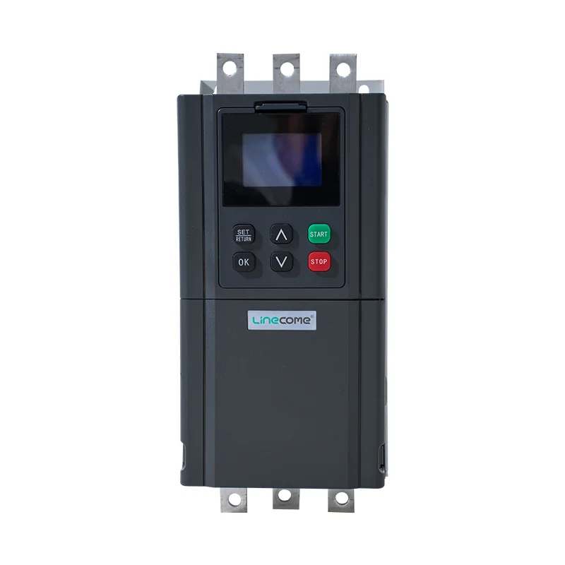
The related NR1000 starter above illustrates another size in the website’s product family. It is a product reference for the documentation discussion, not proof of an installed reversing arrangement or an interchangeable terminal schedule.
A decision table for phase-related observations
Use this table to organize evidence before making a change. It describes investigation priorities and does not replace the starter’s fault procedure.
| Observation | Evidence to obtain first | Question to resolve |
|---|---|---|
| Sequence alarm before starting | Exact event, supply measurement point and configured protection | Does the actual supply match the documented requirement? |
| No sequence alarm, wrong rotation | Motor connection record and defined viewing position | Is the complete motor branch consistent with the required machine direction? |
| Phase-loss indication | Event timing and supply/motor-path checks | Is a phase absent or interrupted rather than merely in a different order? |
| Correct direction before a supply change | Previous acceptance record and new source details | Has the change invalidated the earlier verification? |
| Direction problem after maintenance | Replaced cables, terminals, starter or motor | Which controlled connection changed? |
| Reversing operation requested | Exact starter capability and approved power/control design | Is this an engineered reversing application rather than a setting change? |
The table is an acceptance-planning aid. Test limits, permitted settings and corrective connections come from the equipment documents. For a phase-loss investigation, use the separate soft starter phase-loss guide so a supply interruption is not confused with phase order.
Read the manual’s feature boundaries carefully
An available phase-sequence setting may control whether the starter accepts an incoming order. That does not necessarily mean it actively reverses motor rotation. Write down the parameter’s stated function rather than paraphrasing it as a general direction command.
Also distinguish protection options from power-circuit capabilities. A manual might describe an external reversing arrangement or a special feature that applies only to certain models. Confirm the required hardware, interlocks and conditions instead of assuming the whole product family shares it.
For an in-line or inside-delta installation, use the diagram for that exact arrangement. Terminal relationships and commissioning checks can differ. This guide intentionally does not tell readers to swap an arbitrary pair of conductors, because the connection topology and manufacturer’s permitted correction point have not been established.
When the documentation is unclear, send the supplier the complete power drawing, model and alarm record. Ask for a marked-up, approved correction and the checks required afterward. An instruction without a stated connection arrangement should be clarified before work begins.
Plan the direction check with the process owner
Decide whether motion is permissible, which area needs to be clear, and which process conditions must exist before energization. A short movement can still matter to a pump, conveyor or other directional load. The process owner’s approval and equipment instructions should define the conditions of the check.
Do not assume that disconnecting a load is always possible or that running a pump briefly without its normal conditions is harmless. Where uncoupled testing is proposed, it needs its own mechanical and electrical plan. Where coupled testing is required, address the driven equipment’s limits before applying a start command.
Write the start authority, observation position, stop method and maximum permitted test extent into the procedure. Define what will make the team stop and investigate. These details keep a direction check from turning into an unplanned attempt to accelerate a machine whose behavior is still uncertain.
HSE guidance for electrical equipment work calls for planned work, secure isolation of energy sources and competent personnel. Mechanical, hydraulic and pneumatic energy can matter alongside electrical energy in this task. Arrange the work around the whole machine rather than the starter enclosure alone.
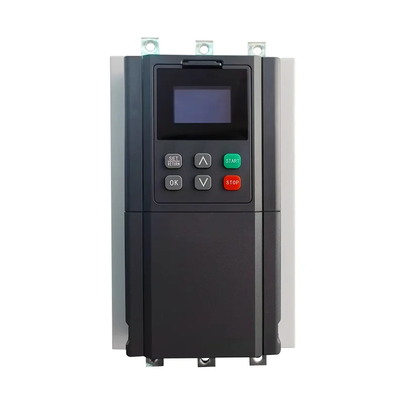
This further NR1000 product reference shows another catalogue size. The photographs support product identification only. Neither exterior appearance nor a power-range title establishes the acceptable starting duty, direction control or protection settings for a particular machine.
Capture the observation rather than only a pass mark
Record the supply source, measurement point, motor and driven-equipment identifiers, drawing revision and starter settings used in the check. Include the required direction and the observer’s viewing position. Then record what actually happened and whether the test stopped normally.
If the result is wrong, preserve the evidence before altering the installation. A corrected drawing should identify the authorized change, who approved it and which previous observations are no longer valid. Repeating the same brief start without changing the diagnosis adds risk and little useful information.
After an approved correction, repeat the affected acceptance checks. That may include supply verification, controlled direction observation and the subsequent normal-start sequence. Follow the equipment documents for what must be repeated; a single successful motion does not validate all starter protections or the complete process.
Retain both the original failure and the final result in the commissioning file. A record that only shows the last pass can hide the reason the connection differs from an earlier drawing. Maintenance needs the current as-built arrangement and the explanation for any approved deviation.
Example: a replacement supply changes the evidence
Consider a machine whose commissioning file records correct rotation on the original supply. Later, the plant changes its upstream source or feeder. The operator sees a phase-sequence indication before starting and asks whether it can simply be disabled.
The first response is to compare the new supply condition, the recorded settings and the exact event with the approved design. The old direction record describes an earlier configuration. It should not be used as proof that the changed installation is ready to run.
If the designer approves a correction, the team updates the drawing and follows the defined verification process. If the supplier confirms that a configuration option is appropriate, that written confirmation should explain the permitted application and the checks that remain. Neither route should be treated as automatic authorization to bypass a protection function.
This example specifies no parameter number, delay or conductor swap. Those details belong to the actual starter and machine. The lesson is to preserve the distinction between identifying the new condition, selecting a permitted response and proving the resulting installation.
Keep rotation, bypass and starting performance separate
A successful direction check does not establish that the motor accelerates correctly under its intended load or that the bypass sequence is healthy. These need their own records and acceptance conditions.
The soft starter operating-sequence guide describes the wider start/run/stop relationship. The bypass-contactor diagnostic checklist covers command and feedback problems in that separate part of the system. Use those records alongside the direction check without merging their conclusions into one vague “starter tested” statement.
Similarly, a correctly rotating motor does not prove overload protection, short-circuit coordination or mechanical process suitability. The handover package should identify which tests have actually been performed and which remain open. This makes an incomplete commissioning stage visible before production use.
What to request with a new starter or retrofit
Provide supply information, the motor nameplate, connection arrangement, driven-equipment direction requirement and starting duty. State whether only one direction is required or whether reversing is part of the specification. Include existing drawings and any change in supply source, motor or cable.
Ask for the delivered model’s manuals, available sequence-related functions, proposed settings and approved connection drawings. Request the supplier’s test and acceptance recommendations for the actual topology. For a reversing application, require the complete engineered arrangement rather than a promise that the starter can “run both ways.”
The final handover should contain the as-built drawing, setting backup, event history, direction observation and normal operating checks. Apply the safety requirements for the installation jurisdiction alongside the equipment instructions. A general safe-work procedure does not replace the starter manufacturer’s connection instructions.
Video: the rotating magnetic field
The MIT Physics demonstration below makes the rotating-field principle visible. It supports understanding the difference between three-phase supply order and a software command. It is a physics demonstration, not a safe method for testing a connected industrial machine.
Video by MIT Physics Instructional Resources Lab. Watch Magnetic Rotor/Tesla's Egg (H27) [5K40.60] on YouTube.
Frequently asked questions
Is a phase-sequence alarm the same as phase loss?
No. Phase sequence concerns supply order, while phase loss concerns an absent or interrupted phase. Read the exact event and follow the model-specific procedure before deciding which condition is present.
Does accepting either sequence guarantee correct motor direction?
No. Acceptance of the incoming supply and the required direction of the connected machine are separate checks. Confirm the approved connection and observe direction under the equipment-specific commissioning procedure.
Can a soft starter reverse the motor through a setting alone?
Do not assume that capability. Conventional soft-start operation and engineered reversing or special slow-speed functions have different requirements. Obtain the exact model’s documented capability and approved power/control arrangement before specifying reversal.


