




Pump float switch control must define whether the pump fills or drains a vessel, the level that starts it, the different level that stops it, and the response to a failed signal. A float contact alone does not describe the complete operating sequence. For drainage, a rising level normally requests a start and a lower level ends the cycle. For filling, a low level normally requests a start and the upper target ends it. Verify the actual contact states and controller logic before accepting either arrangement.
This guide covers discrete level commands and cabinet acceptance. It does not supply a universal float wiring diagram, pump cycling limit or safe liquid depth. Those decisions depend on the liquid, vessel, pump, electrical design and consequences of overflow or dry running.
Write the fill or drain sequence in plain language
Start with one sentence describing the process: “remove water from this sump” or “fill this storage tank from that source.” Then name the measured vessel. A low level in the destination tank may request filling, while a low level at the source may prohibit the same pump from running. Confusing those locations can reverse the intended protection.
List the normal start condition, normal stop condition and conditions that inhibit operation. Identify the required action when automatic mode is selected and when power returns. Operators should be able to predict the result without interpreting a wiring diagram or guessing the meaning of an unlabeled float.
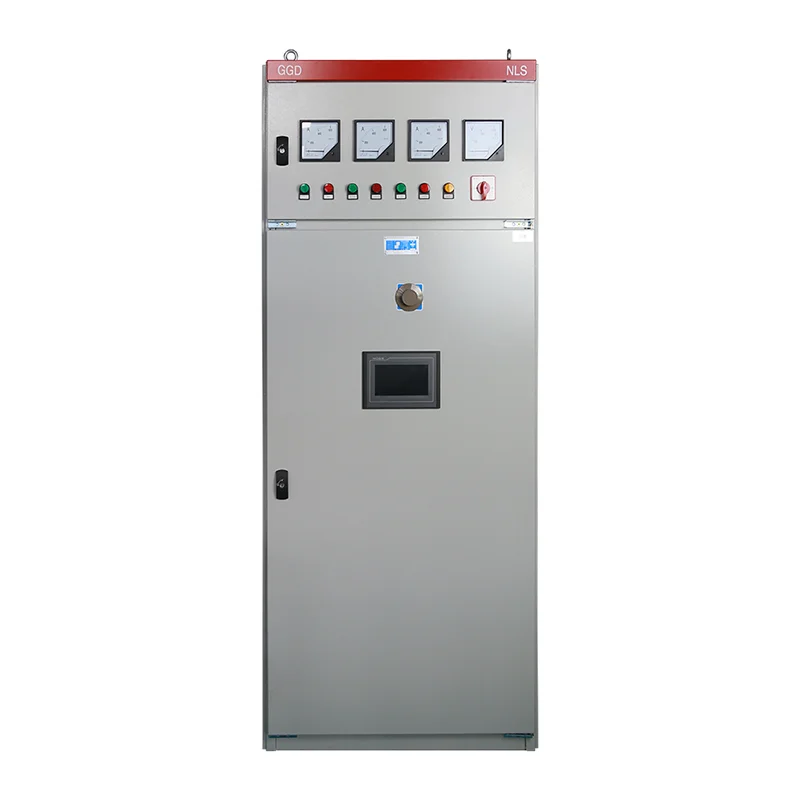
The LINECOME pump control cabinet describes manual and automatic operation and float-related control applications. Confirm the ordered configuration, terminal allocation and cause-and-effect schedule with the supplier. A catalog description covering several arrangements does not establish which sequence or alarms are included in a particular cabinet.
Separate point detection from continuous measurement
A float switch usually reports a state associated with a level or movement range. It does not necessarily report the actual liquid height. Two contacts at different elevations can establish a working band, but the controller still needs a defined rule for what happens between them.
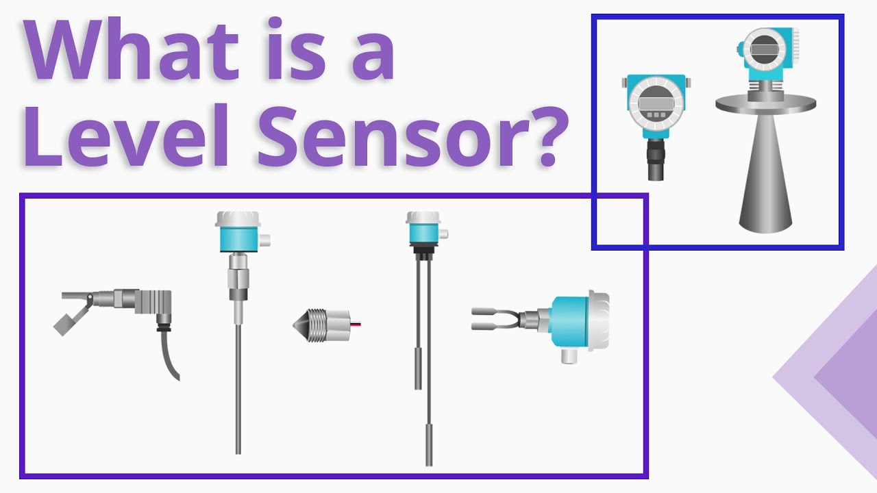
The RealPars overview of level sensors explains the distinction between point and continuous sensing. Select the sensing method for the process rather than assuming every tank needs the same instrument. Fouling, turbulence, access and the liquid’s properties affect whether a proposed float arrangement is suitable.
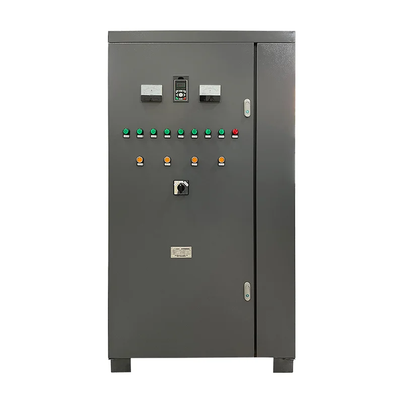
For a PLC-based implementation, review the role of a PLC control cabinet. The program must distinguish demand, permission and actual pump-running feedback. An illuminated input indicator proves only that the controller sees a state; it does not prove the pump is moving liquid or that the float is at the correct elevation.
Establish a useful start-stop band
Separate start and stop levels prevent the pump command from following every small surface movement. The useful operating volume lies between those elevations, subject to vessel geometry and the control method. A narrow band may produce frequent cycling; a wider band may conflict with the permitted operating levels or required reserve volume.
The Connecticut drainage guidance on pump stations links sensor settings and storage volume to pump cycling. Use that design relationship as a reason to request project calculations, not as a source of a universal elevation difference. The pump’s permitted duty and the site’s hydraulic behavior must be checked together.
Record the level reference on the drawing. Specify whether dimensions are measured from the vessel floor, a survey datum or another fixed point. A statement such as “set the upper float higher” cannot be reproduced after maintenance. The final record should allow a replacement technician to restore the approved arrangement without trial-and-error operation.
Check the electrical interface before assigning terminals
Verify the float’s contact arrangement, permitted voltage and switching duty, cable suitability and installation instructions. Do not infer the contact function from wire colors or a generic online drawing. The same mechanical position may produce a different controller interpretation when the selected contact or program logic changes.
A control contact must be suitable for the circuit it switches. Where it operates a relay, contactor or PLC input, use the electrical designer’s approved interface. Do not connect a float directly to a motor merely because the contact appears to close reliably during a bench check. Starting current, inductive switching and electrical protection require their own assessment.
Any terminal inspection or alteration requires competent personnel, safe isolation and the appropriate verification. This article deliberately omits live test instructions and terminal numbers. Record an approved circuit reference next to each signal so that the cabinet and field installation can be compared consistently.
Agree the expected result for each level state
Use a cause-and-effect table before commissioning. The example below describes questions to resolve, not a ready-to-download control program. It reflects the distinction between routine level control and abnormal high-water warning shown in the Virginia Department of Health explanation of pump systems. Its domestic effluent context does not establish requirements for every industrial installation.
| Condition to test | Drainage sequence question | Filling sequence question |
|---|---|---|
| Normal start level reached | Is a valid request generated as liquid rises? | Is a valid request generated as destination level falls? |
| Normal stop level reached | Does operation stop before the prohibited low level? | Does operation stop before the prohibited high level? |
| Level between setpoints | Is the previous running state retained as designed? | Is the previous running state retained as designed? |
| Source unavailable | Is dry-running protection effective where required? | Does the source condition inhibit the filling request? |
| Abnormal level | Is the specified alarm and escalation response produced? | Is the specified overflow warning or protective action produced? |
| Signal missing or implausible | Does the documented fault response occur? | Does the documented fault response occur? |
| Power restored | Is restart behavior consistent with the risk assessment? | Is restart behavior consistent with the risk assessment? |
Do not choose a single “fail-safe” contact label and assume all failures are covered. A broken cable, stuck float and controller fault may produce different observations. Define credible failures and test the agreed response without creating an actual overflow or dry-running event.
Keep alarms distinct from normal control
The normal stop point should not be the only evidence considered when an overflow would have serious consequences. Determine whether an independent abnormal-level alarm or protective action is required by the risk assessment and project rules. If independence is specified, document the sensor, power, logic and notification paths that support that claim.
A high-level alarm can be present while the pump remains unavailable. Acceptance therefore needs more than confirmation that a lamp lights. Establish who receives the alarm, what information is displayed and what action is expected. Test acknowledgement separately from removal of the underlying condition.
Where dry-running protection is relevant, distinguish the source condition from destination demand. The separate solar pump dry-run commissioning guide discusses that protection in its own application. A destination float does not automatically establish that sufficient water is available at the pump inlet.
Diagnose short cycling from a recorded sequence
Log the observed levels, input states, output command, actual running feedback and time of each event. This separates a moving float contact from a controller timer, an overload trip or a hydraulic problem. A pump that stops because protection operated is not exhibiting the same failure as a command that oscillates with surface turbulence.
Inspect mechanical freedom and mounting against the float instructions. Look for cable entanglement, fouling, restricted travel or interference from vessel fittings. Review the flow near the sensing location. Moving a float or adding a delay may change the symptom while violating a required stop level, so proposed changes need design review.
Compare the actual start-stop band with the approved elevations and usable volume. Ask whether the operating inflow and pump capacity differ from the design assumptions. Do not invent a generic minimum run time or extend operation below the pump’s permitted liquid level to reduce the number of starts.
Test the sequence before a full wet trial
Begin with a controlled input simulation or other approved test method that avoids unintended pump operation. Confirm the controller’s interpretation of each contact state, then the resulting demand, permissions, command and alarm. Mark simulated checks distinctly so they are not mistaken for a successful pumping test.
A subsequent site test should confirm the physical relationship between liquid level and the installed sensing arrangement. Plan access, overflow management, pump availability and safe stopping in advance. Some vessels and services introduce confined-space, contamination or hazardous-area requirements; the appropriate site procedure governs the work.
For multi-pump systems, use the separate duty and standby cabinet acceptance checklist for staging, alternation and failure transfer. This article’s single-sequence table does not prove that two pumps share duty correctly or that a standby unit will respond when required.
Hand over settings that can be restored
Deliver the final level elevations, float identifiers, mounting details, cable labels and circuit references. Include the approved logic description, any timers, alarm destinations and the tested response after loss of power. Identify settings that operators may change and those requiring engineering review.
Keep the test result connected to a specific cabinet configuration and drawing revision. A later replacement of a float, contactor or controller can change the interface even when the exterior looks unchanged. Retain a concise maintenance check that verifies physical movement and the resulting control state after such work.
Watch the sensor overview
This RealPars educational video introduces level-sensing methods, including point detection. Use it to understand the measurement choice; it does not define the contact wiring, setpoints or safety functions of the cabinet supplied for a project.
Video by RealPars. Watch What is a Level Sensor? on YouTube.
Frequently asked questions
Does one float switch provide both start and stop control?
Some arrangements use a float’s mechanical switching range, while others use separate level devices and controller memory. Verify the actual product instructions and sequence. A single contact symbol does not establish the operating band or failure response.
Why does a pump start and stop repeatedly near one level?
Possible causes include insufficient operating band, turbulence, restricted float movement, a wiring fault or different controller logic than intended. Record level and signal states before changing the installation. Pump protection and hydraulic faults can also interrupt a cycle.
Can the high-level alarm share the normal control float?
That depends on the specified risk controls and required independence. A shared float can create a common failure path. Where independent warning is required, verify the complete alarm arrangement and its tested response rather than relying on a second software label.


