




Soft starter voltage unbalance should be investigated by comparing the three line-to-line voltages at defined locations and operating states, rather than treating every unequal output reading as a supply fault. A soft starter changes the motor waveform during starting, so supply-side quality, starting behavior and steady running need separate records. Preserve the fault information, confirm the measurement method and trace where the asymmetry appears before changing protection settings. A starter cannot be assumed to correct an unbalanced supply, and an apparently acceptable average voltage does not show that all three phase relationships are healthy.
Define the complaint before changing settings
Write down what actually happened: a voltage-related alarm, an overload trip, slow acceleration, vibration or a difference between measured values. Include when the symptom occurs, how long the motor runs and whether other equipment changes state at the same time. The fault name alone may not identify the cause. A starter alarm reflects the detection method and settings of that device; it is not automatically the same calculation used in an external power-quality report.
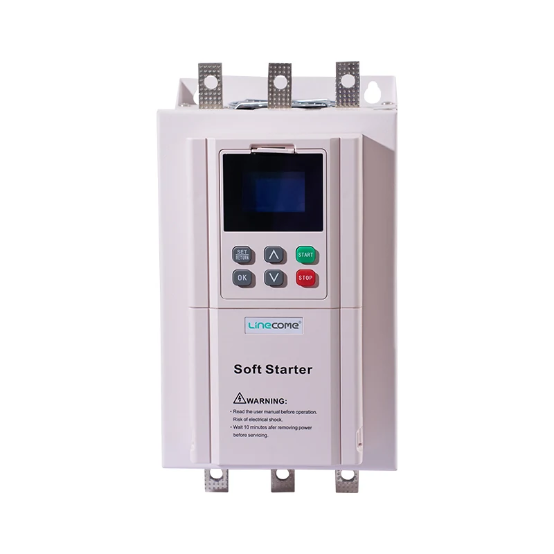
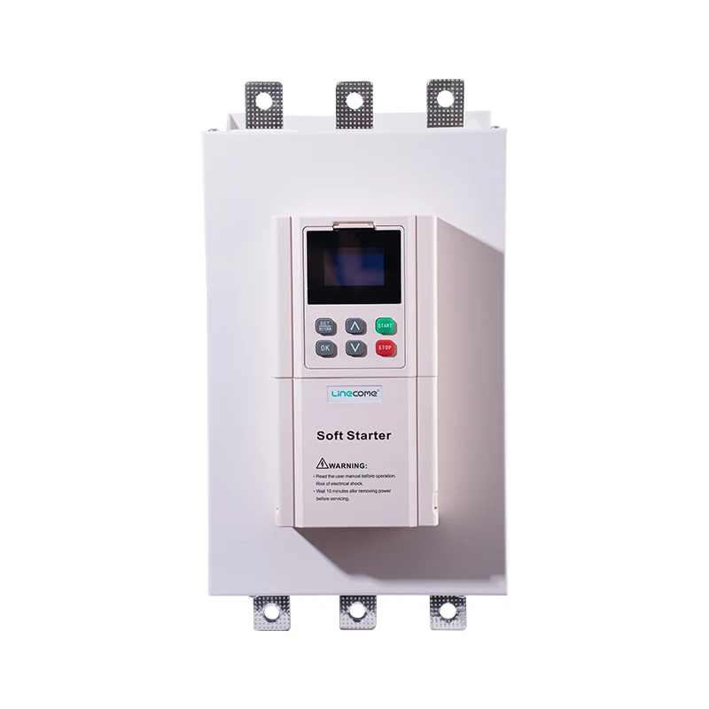
The ZR900 online soft starter product page identifies the product family illustrated here. Obtain the supplied model’s actual instructions, protection functions and approved circuit arrangement before making a settings decision. The photograph does not establish a voltage-unbalance threshold, measurement algorithm, bypass arrangement or motor derating factor. For the general starting sequence, see how a soft starter works. This article focuses on distinguishing supply quality from waveform and operating-state effects.
Keep voltage unbalance, phase loss and phase sequence separate on the investigation form. They can produce overlapping symptoms but describe different conditions. A complete missing supply path needs its own investigation; reversed phase order is not the same as unequal voltage magnitudes. Use the soft starter phase-loss guide if the evidence points to an interrupted path. Avoid turning every three-phase complaint into a generic “phase fault” with no recorded measurements.
Establish a comparable measurement plan
Identify the points on the approved single-line and control drawings: upstream distribution, starter supply terminals and motor circuit. Record the operating state for each reading, including stopped, accelerating and stable running. A result at one location during a light-load condition cannot be directly compared with another location during a heavy start. Where the symptom is intermittent, plan how to capture the same event rather than relying on separate spot readings taken at convenient times.
Electrical measurements must be planned and performed by qualified personnel using equipment appropriate to the circuit, expected waveform and hazard. Follow the applicable site procedure and governing requirements. OSHA’s electrical work-practice requirements are a public reference for isolation and energized-work boundaries. This article does not instruct an unqualified operator to probe live terminals, exchange phases or bypass protection to obtain a comparison.
Specify whether the instrument reports true RMS, a fundamental component, a sequence-based unbalance metric or a manufacturer-defined value. Those quantities may answer different questions. Record instrument identification, range, connection arrangement and relevant settings. If a waveform is chopped or distorted, confirm that the instrument and method are suitable before interpreting the number. A familiar display with a voltage symbol is not sufficient evidence that two instruments are measuring the same thing.
Calculate line-voltage unbalance with clear units
The U.S. Department of Energy voltage-unbalance tip sheet describes a calculation using the largest absolute deviation from the mean of three line-to-line voltages. This gives a practical magnitude-based screening value. It is different from assuming that a starter’s internal alarm uses that exact method. For distorted starting waveforms, establish the appropriate assessment method with the equipment and motor specialists.
Write V_avg = (V_AB + V_BC + V_CA) / 3. Then calculate unbalance (%) = 100 × max(|V_AB − V_avg|, |V_BC − V_avg|, |V_CA − V_avg|) / V_avg. The voltage inputs and average must use the same unit, normally volts. The result is a percentage. Do not divide by the nominal supply rating or use only the difference between the highest and lowest reading; those substitutions produce a different metric.
As an original arithmetic example, suppose a qualified test records 398 V, 402 V and 400 V under the same defined steady operating condition. Their mean is 400 V and the largest deviation is 2 V. The calculated magnitude unbalance is therefore 100 × 2 / 400 = 0.5%. These hypothetical readings demonstrate the calculation only. They do not establish acceptance for a particular motor, starter or site, nor prove that an acceleration waveform has been correctly assessed.
Use nonzero, valid readings from the same three-phase set. Missing data, inconsistent measurement locations or a changing load can make the calculation misleading. Rounding should not hide a value near the project’s action limit; retain the underlying readings and the instrument’s uncertainty. Where a power-quality analyzer reports a different definition, label both metrics rather than forcing them into one unlabeled percentage column.
Trace where the asymmetry appears
Use the following original diagnostic planning table to organize the next investigation. It does not supply a universal limit or authorize live troubleshooting. The DOE reference supports reviewing supply unbalance; the measurement location and corrective action still require the approved project method and equipment documents.
| Recorded pattern | What it suggests reviewing | Evidence needed next |
|---|---|---|
| Unequal supply readings across several loads | Incoming supply and shared distribution | Comparable upstream records and load states |
| Symptom appears when another branch starts | Shared impedance or changing loading | Event timing and simultaneous voltage record |
| Difference appears across a local circuit section | Connections, switching devices and conductors | Approved inspection and electrical test results |
| Unequal readings only during acceleration | Waveform, control topology and instrument suitability | Correct method and starter-specific interpretation |
| Voltage and current evidence disagree | Measurement definitions and motor condition | Comparable three-phase readings and specialist review |
| Symptom disappears before investigation | Intermittent operation or changed conditions | Preserved alarm log and event capture plan |
Treat a comparison as a direction for investigation, not proof of a failed part. A local voltage difference may lead to inspection of a connection or switching device, but replacement should follow confirmation. Record the circuit location and operating condition precisely enough that another engineer can repeat the check. “Bad voltage at the motor” is not a useful handoff if the report omits whether the starter was accelerating or already running.
Keep starting and steady-running evidence separate
During starting, phase-controlled semiconductor switching changes the voltage waveform delivered to the motor. The behavior depends on the starter design and its operating stage. An output measurement during the ramp should therefore not be treated as a simple copy of the incoming sinusoidal supply measurement. Confirm the supported test method before applying a familiar steady-supply calculation to that output.
Create separate columns for supply voltage, output observations, motor current and starter state. If an installation has a bypass path, establish from the approved drawing when it is active and which sensing functions remain in the relevant circuit. Do not infer the current path from a product photograph or the word “online.” The soft starter current measurement guide covers that separate measurement-chain question and helps prevent comparisons between incompatible meter locations.
Avoid using one phase reading to declare three-phase quality acceptable. Likewise, do not average away an unusual phase to make the overall supply appear close to nominal. Preserve the complete set, together with load and state information. If the motor is overheating despite apparently balanced voltages, the investigation should also consider load, cooling, motor condition and measurement limitations. Voltage symmetry is one part of the evidence, not a complete motor-health certificate.
Connect the result to motor acceptance
Small voltage differences can have important motor consequences, but the relationship is not a fixed multiplier for every installation. The ASHRAE chapter on motors and controls discusses the connection between unbalanced voltages, unequal currents and heating. Use the actual motor manufacturer’s requirements and the applicable project criteria to decide whether corrective work, derating or additional analysis is needed. Do not transfer a derating curve from an unrelated machine into a starter setting.
Keep the motor and starter acceptance questions distinct. A starter may remain powered and display no alarm while the operating condition still requires motor review. Conversely, a protection alarm should not be disabled merely because a handheld calculation looks low. Establish how the protection works, whether its sensors and configuration match the circuit, and what evidence the motor specialist needs. An alarm threshold is not a general permission to operate indefinitely just below it.
If production pressure makes repeated restarting tempting, preserve the protection boundary. Additional attempts can consume motor thermal capacity and obscure the original event. Follow the approved restart policy and investigate an unresolved condition. The decision to resume service belongs to the responsible personnel with access to the actual equipment history, operating limits and test results. A generic article cannot provide that authorization.
Verify corrective work with a controlled comparison
Possible actions may involve supply coordination, redistribution of single-phase loads, repair of a confirmed defective connection or correction of a documented configuration error. Choose the action from the evidence. Do not randomly tighten, swap or replace parts while leaving the investigation record unchanged. Deenergized inspection and repair must follow the correct isolation, torque and equipment instructions; a general troubleshooting table is not a repair procedure.
After corrective work, repeat the agreed measurements at the same locations and comparable load conditions. Retain both before and after records. Include acceleration and stable running where relevant to the complaint, plus checks of alarms and the approved operating sequence. If the original event depends on another load starting, reproduce that condition within the authorized test plan. A quiet no-load test cannot close an investigation of a heavy-load event without further reasoning.
For a service inquiry, provide the motor nameplate, starter model, circuit drawing, operating duty, alarm history and full three-phase measurement set. State the instrument method and exactly when readings were taken. Ask which assessment method, action criteria and additional tests apply to that combination. This gives the supplier a concrete engineering question and reduces the chance of receiving a generic recommendation to increase a protection threshold.
Further learning: what the starter changes
The RealPars soft-starter lesson below introduces the principle of controlled motor starting. It helps explain why starting and steady-running observations should be distinguished. It does not establish voltage-unbalance protection settings or the permitted measurement method for the pictured ZR900 product. Use the approved motor and starter documents for those decisions.
Video by RealPars. Watch What is a Soft Starter? (For Absolute Beginners) on YouTube.
Frequently asked questions
Does a soft starter correct an unbalanced incoming supply?
Do not assume it does. Investigate the supply and distribution condition, then verify the motor and starter requirements for the actual operating state and equipment combination.
Can unequal ramp-output readings prove that the supply is unbalanced?
No. The starting waveform, control arrangement and instrument method can affect output readings. Compare correctly measured supply-side evidence and keep acceleration records separate from steady-running data.
Should the voltage-unbalance trip threshold be raised to keep production running?
Do not raise it without an engineering review of the measurement, protection function, motor limits and cause. Preserve the alarm record and correct the verified problem before accepting normal operation.


