




Control cabinet protective bonding connects the relevant exposed conductive parts into the protective circuit specified for the assembly. Before handover, trace that circuit from the incoming protective connection through the cabinet’s documented bonding points, inspect its construction and obtain the required verification results. A green-and-yellow conductor, a metal hinge or a continuity buzzer alone does not demonstrate that the complete arrangement meets the project requirements. This guide provides a review and evidence checklist for qualified personnel; the approved design, applicable standards and equipment instructions determine the actual connections and test criteria.
Define the cabinet boundary and the protection arrangement
Start with the approved electrical drawing and the installation scope. Identify the incoming protective terminal, cabinet structure, mounting plates, doors, removable panels and outgoing protective connections. Also identify assemblies supplied separately and connections completed at the destination. A factory record cannot verify a site connection that did not exist when the test was performed.
For a variable-frequency control cabinet, request the protective-circuit drawing and verification scope for the supplied assembly. The exterior photograph does not reveal the installed bonding conductors, contact surfaces or test results. A catalogue description of the enclosure or drive does not replace evidence for the completed cabinet.
Establish the supply arrangement and applicable equipment requirements with the responsible designer. Protective bonding, system grounding and neutral arrangements are related but distinct matters. Do not add a neutral-to-enclosure connection based on a photograph of another installation or advice intended for a different supply system.
Separate protective bonding from functional grounding
Protective bonding concerns protection against electric shock under the conditions defined by the applicable design. Functional grounding and bonding can serve signal references or electromagnetic performance. A cable shield connection may be important for communication quality without being an adequate replacement for a required protective conductor.
The official IEC 60204-1 publication description identifies protective bonding within the scope of machine electrical equipment. It also identifies separate electromagnetic-compatibility requirements. The public description establishes the standard’s subject; it does not provide the full project-specific test procedure or demonstrate compliance of a particular cabinet.
Keep the drawing symbols and terminal labels clear. Record which connections form part of the protective circuit and which serve other functions. Where one construction performs more than one role, obtain the design justification. Do not remove a protective connection to improve a noise symptom; investigate the signal and installation arrangement through an approved process.
Trace the path rather than counting visible straps
Work systematically from the incoming protective terminal to each point identified on the drawing. Mark each connection on a controlled copy. Include points hidden by removable covers and any connection completed after shipping. Confirm the actual arrangement rather than assuming that similar cabinets were assembled identically.
Inspect the designated contact surfaces, fasteners, terminals and conductors against the instructions. Paint, corrosion, contamination or an incorrect assembly can interfere with an intended conductive joint. The solution must follow the approved construction; indiscriminate scraping, drilling or substitution can damage the enclosure or invalidate its intended performance.
Do not assume that every hinge, DIN rail or mounting screw forms a qualified protective path. Equally, do not invent a universal requirement for an extra wire on every small metal part. The relevant parts and permitted construction depend on the design and applicable requirements. Record uncertain joints for engineering review before acceptance.
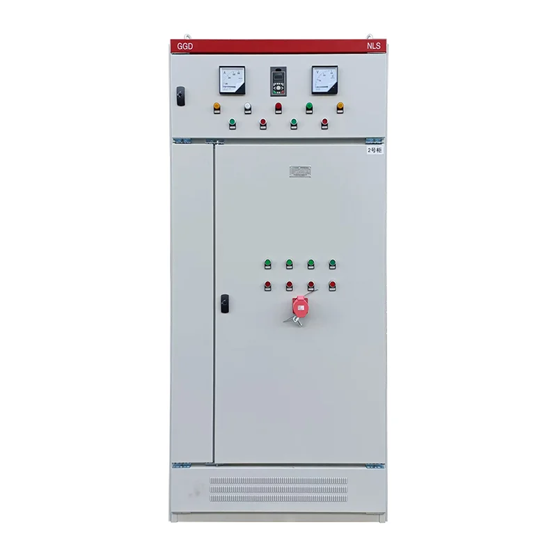
Use a connection checklist with specific evidence
The following is an original handover checklist. It organizes review points without assigning universal conductor sizes, resistance limits or test currents. The responsible engineer must specify the applicable criteria and any exclusions. Photographs should identify the inspected point, while measurement records should identify the path actually tested.
| Review area | Evidence to request | Question to resolve before acceptance |
|---|---|---|
| Incoming protective connection | Drawing, terminal identity and installation record | Is the source connection inside the tested scope? |
| Enclosure structure | Approved joint arrangement and inspection result | Which structural joints carry the protective path? |
| Door and moving parts | Drawing, connection detail and movement inspection | Is the intended path maintained during normal movement? |
| Mounting plate | Specified connection and verified measurement points | Does the test include the plate and its relevant equipment? |
| Removable panels | Assembly instructions and restoration check | Is the connection restored after access or shipping? |
| Outgoing equipment | Terminal schedule and site completion record | Which external paths remain to be verified? |
| Test equipment | Instrument identity, method and calibration status | Is the instrument suitable for the approved verification? |
| Final handover | Results, acceptance criteria and reviewer approval | Are all unresolved points identified and closed? |
For US workplaces, OSHA 1910.304(g)(5) addresses the effectiveness and continuity of the grounding path. Its scope and exceptions must be considered within the actual installation. It does not turn this checklist into a complete international compliance procedure.
Establish a safe condition before inspecting or measuring
Internal inspection and testing require the site’s hazardous-energy-control arrangements. Identify every electrical source, including separate control supplies, stored energy and possible backfeeds. A stopped drive or an open door interlock does not establish that the cabinet is safe to touch. Qualified personnel must follow the applicable isolation and verification instructions.
The CCOHS lockout guidance explains the general need to identify and control hazardous energy. Use it alongside the site procedure and supplied equipment instructions. This article does not authorize energized testing or prescribe a discharge interval for an unidentified drive.
Before connecting an instrument, review its method and the equipment that could be affected. Do not disconnect a protective path while the system remains in service merely to obtain a convenient isolated reading. If the approved method requires a temporary disconnection, the work plan must address the safe condition, restoration and subsequent verification.
Specify what a continuity result actually demonstrates
A measurement is meaningful only when the tested endpoints, circuit condition, instrument and acceptance criteria are known. Record the incoming reference point and the exact remote point. A result measured on a nearby clean screw does not necessarily include the joint that the drawing requires to be verified.
Choose the test method and limits from the applicable standard edition and approved procedure. A handheld meter’s audible indication can assist fault-finding, but it does not automatically satisfy a specified protective-bonding verification. This guide intentionally does not assign one resistance limit to every conductor length, material and assembly.
Consider parallel conductive paths when interpreting results. A low reading through an unintended parallel route can conceal a defective designated connection. The test engineer should define how the intended construction is assessed without compromising safety or damaging connected equipment. Record limitations rather than treating every low reading as conclusive proof.

Check movement, maintenance and transport interfaces
Inspect door connections through the permitted range of normal movement. Look for mechanical strain, abrasion, trapping and loosened terminations. A connection that is satisfactory with the door partly open may be damaged when the door reaches its full travel. The approved conductor and routing arrangement should accommodate the intended movement.
Review removable panels and modules that maintenance staff are expected to handle. Identify any connection that must be restored after access, and provide clear instructions for doing so. A connection hidden behind an unlabelled cover is easy to omit during later work even if the original factory assembly was correct.
Shipping can separate cabinet sections, remove doors or leave protective links for site completion. List those interfaces in the dispatch and commissioning documents. Repeat the applicable inspection and verification after reassembly. Keep the factory results as evidence of the factory scope, while documenting the final installed condition separately.
Treat a failed result as a construction problem to resolve
When a result fails the approved criterion, identify the affected path and preserve the original observation. Check the drawing, assembly detail, instrument setup and connection condition. Do not simply choose a different measurement point until the instrument displays a smaller number. That can hide the actual defect from the next reviewer.
Any repair should use the approved component, termination and assembly method. Record what changed and why, then repeat the relevant verification. Where a structural joint or coating detail differs from the design, obtain an engineering disposition instead of making an undocumented workshop modification.
After repair, consider whether the work affects other properties of the assembly, including enclosure sealing, mechanical strength or adjacent wiring. The site’s control cabinet IP rating guide explains a related enclosure boundary. Protective bonding and ingress protection require separate evidence; improving one does not excuse damage to the other.
Include the external equipment and maintenance record
A cabinet can pass its internal verification while the outgoing protective connection to a motor or machine remains incomplete. Clearly state where the cabinet supplier’s scope ends and the installer’s scope begins. Assign responsibility for the final system checks so the gap is visible before energization.
For a broader acceptance package, the PLC cabinet FAT checklist helps organize related documentation and functional tests. Retain a dedicated protective-circuit record with the tested points, method, results, criteria, date and responsible person. A general “electrical test passed” statement is difficult to audit or repeat.
Use the VFD cabinet overview to identify the relevant cabinet category, then request the project-specific construction and verification documents. Keep approved drawings current after later modifications. A replacement door, gland plate or cabinet section should trigger review of the affected protective connections before return to service.
Educational video: distinguish grounding functions

Video by RealPars. Watch Electrical Grounding Explained | Basic Concepts on YouTube.
RealPars introduces grounding concepts and the different meanings of ground in electrical systems. It supports the distinction between protective connections and signal references. It is not a cabinet certification procedure or an instruction to change neutral bonding or remove protective conductors.
Frequently asked questions
Does a metal door hinge automatically prove protective bonding?
No. Whether the intended construction provides an acceptable path depends on the approved design and applicable requirements. Inspect and verify the specified arrangement rather than assuming a hinge is sufficient.
Can a cable shield replace a required protective conductor?
Do not assume so. Signal shielding and protective bonding have different purposes and construction requirements. Follow the approved circuit and equipment instructions.
Is a factory test enough after cabinet sections are reassembled on site?
It covers only the tested factory arrangement. Connections made or disturbed during transport and installation need the applicable final inspection and verification before acceptance.


