




RS485 termination in PLC cabinets should be checked at the physical ends of each communication segment, not at every cabinet or every device. Trace the actual cable route, identify existing termination networks and confirm the port instructions before adding a resistor. Review biasing separately: termination controls reflections, while biasing establishes an idle condition for equipment that requires it. A working Modbus register map cannot compensate for an unstable electrical connection. This guide provides a practical inspection and acceptance sequence without assuming that the cabinet exterior reveals the installed communication hardware.
Draw the complete segment before touching a switch
List the controller or gateway and every connected device. Show the trunk route, intermediate connections, branches, repeaters and the two physical cable ends. A cabinet boundary is not automatically a bus boundary. A cable can enter a PLC panel, continue through its terminals and leave for another panel several buildings away.
For a PLC control cabinet, ask for the supplied port or module identity and the approved network drawing. Confirm whether RS485 is actually included; a cabinet family name does not establish a protocol, connector, isolation arrangement or electrical interface. Record interface options and fitted accessories separately from the enclosure product description.
Include temporary service connections on the drawing. A programming adapter or replacement gateway can introduce termination or bias that disappears when the technician leaves. If the network works only while a laptop interface is connected, that observation deserves investigation rather than acceptance as a permanent repair.
Separate the physical interface from Modbus settings
RS485 describes an electrical communication interface. Modbus RTU defines a serial messaging arrangement used over it. Both layers need correct configuration. Check the physical connection independently from device addresses, serial settings, function codes and register interpretation.
A useful first distinction is whether valid responses are received consistently. Frequent communication errors suggest a different investigation from consistent, valid responses containing an unexpected value. Neither observation proves one cause, but they prevent changing a register offset to solve a wiring problem or adding resistors to solve a data-format problem.
The Modbus Organization’s serial-line guide covers the physical network and documentation requirements. Apply the relevant arrangement together with the supplied device manuals. Do not assume that every network carrying the Modbus name uses the same physical interface; Modbus TCP over Ethernet requires a different review.
Identify where termination is already installed
At each physical endpoint, inspect the approved drawing and the actual connector, DIP switch or module setting. Termination may be internal, selectable or provided by an external network. Some connectors combine several functions. Record the exact switch position and what the manual says it activates.
For an ordinary terminated two-wire segment, the terminating networks belong at the two cable ends. Intermediate devices should not acquire additional end termination merely because they are inside separate cabinets. Repeaters can divide a system into separate electrical segments, each requiring its own design review.
Texas Instruments’ RS485 design guide explains that termination must match the transmission cable and that branches affect reflections. A commonly used cable and resistor combination is not a universal instruction to fit the same loose resistor to every port. Equipment with special termination networks must follow its documented design.
Review biasing without confusing it with termination
Biasing and termination can be packaged together, but they answer different questions. The bias network establishes the idle bus condition where required; termination addresses signal reflections. Identify which device or network provides the intended bias and whether other devices include enabled bias resistors.
Avoid a blanket instruction to enable bias at both ends or in every panel. Built-in receiver behavior, external resistor networks and total loading must be considered together. The design should identify the intended bias location and the permitted settings of the remaining nodes. If that information is missing, obtain it before changing multiple switches.
Record power dependence as well. A network may behave differently when a device providing bias is switched off for maintenance. The acceptance plan should include the intended operating combinations rather than assuming that all equipment will remain powered continuously. Do not remove protective earth connections to investigate a communication problem.
Use an inspection table that separates questions
The following original checklist organizes the review. Its technical basis is the Modbus serial-line guide and the TI design guide linked above; it supplies no universal resistor value, cable length or device-count allowance.
| Check | Evidence to collect | What to resolve before acceptance |
|---|---|---|
| Segment identity | Route drawing and repeater boundaries | Which cable ends belong to this electrical segment |
| Termination | Port manuals, fitted networks and switch positions | Whether each intended endpoint is correctly terminated |
| Biasing | Enabled networks and port receiver information | Which arrangement establishes the intended idle state |
| Signal naming | Terminal definitions from both devices | How the manufacturer’s labels map to the same signals |
| Reference and screen | Cable specification and bonding instructions | Approved reference and shield connections |
| Branches | Actual trunk and drop arrangement | Whether the route meets the equipment design constraints |
| Serial configuration | Address, baud rate, parity and stop-bit records | Whether all participants use compatible settings |
| Acceptance | Test duration, operating states and error counters | Whether communication remains stable under agreed conditions |
Label ambiguities require particular care. Do not wire solely by matching the letters A and B across unrelated products. Read the terminal definitions and signal conventions in both manuals, then document the mapping. Make any correction through a controlled, safely isolated procedure; random wire swapping creates an unreliable maintenance record.
Inspect cable routing and reference connections
Follow the specified communication cable construction and routing. Keep the trunk recognizable so later additions do not turn it into an undocumented collection of branches. Review proximity to motor and switching-power conductors against the cabinet and interface instructions rather than inventing a universal separation distance.
Distinguish the communication reference, cable screen and protective earth. They serve different functions and cannot be interchanged casually. Check the approved bonding and isolation arrangement across equipment, particularly where remote panels have different grounding conditions. The port’s permitted electrical conditions still matter even when differential signaling improves noise tolerance.
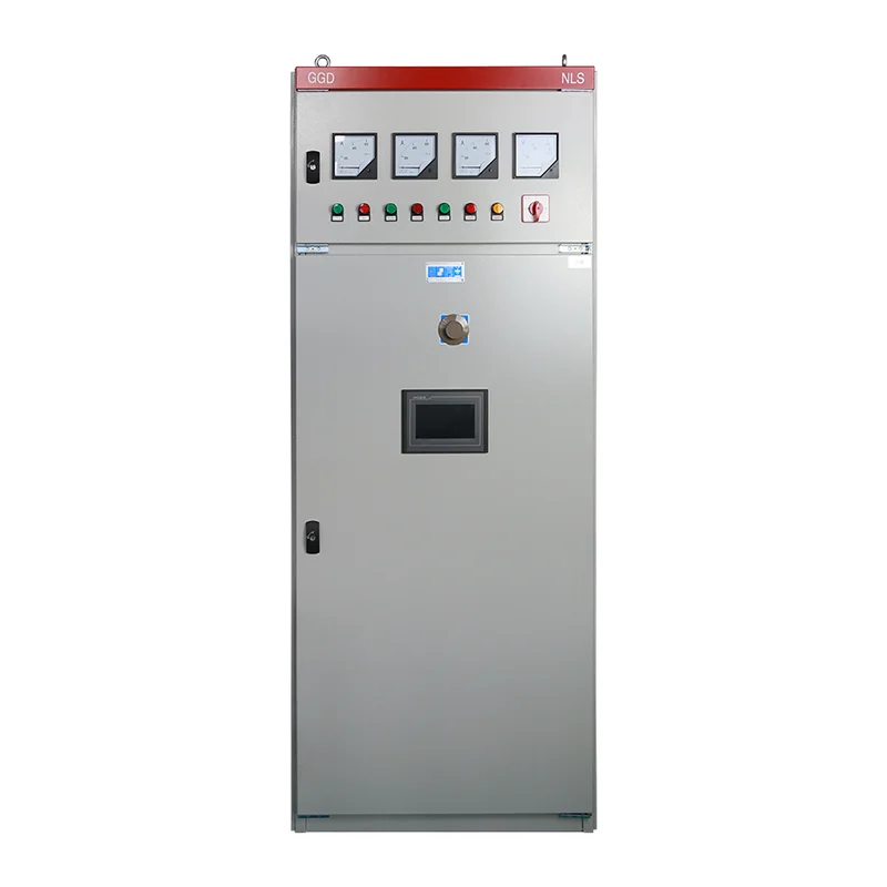
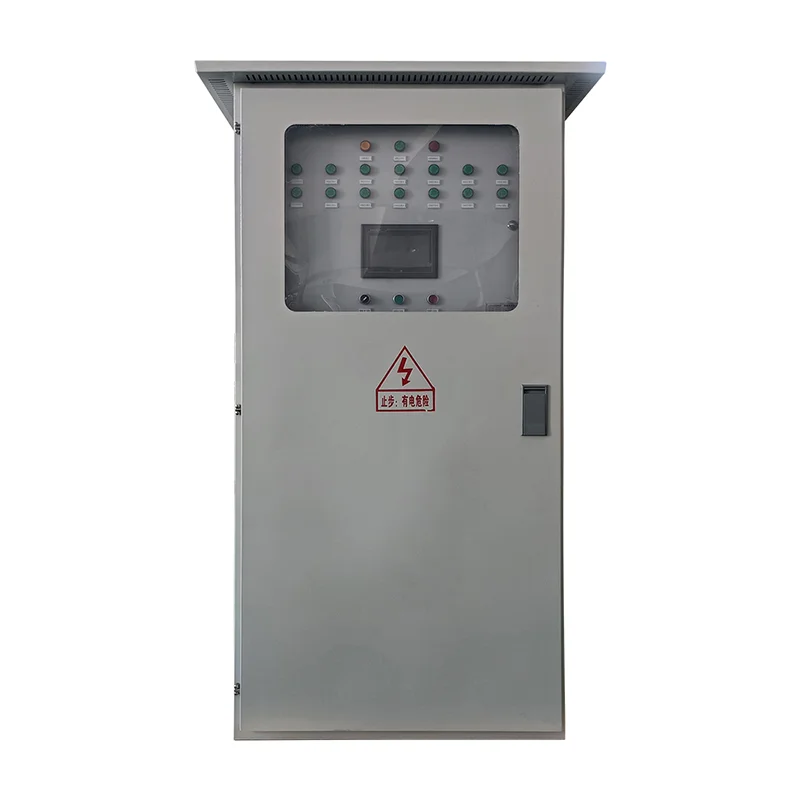
An exterior product photograph cannot show these internal connections. Use the PLC cabinet overview to understand the assembly boundary, then require drawings and port documentation for the actual supplied system. Related cabinets illustrate construction choices, not proof of a fitted RS485 module or an approved network topology.
Start diagnostic testing with a documented baseline
Save current configurations and the initial error counters if the equipment exposes them. Record the observed symptom, affected nodes, operating state and recent changes. A network that fails only when a drive accelerates needs testing under that condition, not only while the machine is idle.
Where practical and authorized, verify communication with a controlled subset of the network before restoring the complete route. Document any removed branches and temporary equipment. A successful short connection demonstrates only that limited arrangement; it does not validate the field trunk, installed termination or full operating environment.
Use a qualified person and an approved procedure for electrical measurements. An oscilloscope connection can introduce grounding hazards or disturb the circuit if the probe arrangement is unsuitable. A handheld resistance reading on a de-energized network can be a diagnostic clue, but connected electronics and bias networks can alter it. Do not treat one resistance value as a complete acceptance test.
Change one supported cause and test the complete system
If the drawing shows an extra termination at an intermediate node, first confirm the exact switch function and obtain authorization for the correction. Save the original position and the expected result. After the change, compare communication behavior under the same test conditions.
Do not simultaneously replace the cable, change the baud rate, enable several bias switches and extend the response timeout. That approach may hide the original defect. A longer timeout can reduce visible alarms without correcting corrupt messages or lost responses. Separate any intentional polling change from the physical wiring correction.
Restore the final production route and remove temporary adapters before concluding. Check every required node, including the farthest connection and the operating combinations defined by the project. Record errors and retries over the agreed observation period. A single successful poll is insufficient evidence for a machine that must communicate reliably throughout a shift.
Add acceptance tests to the cabinet handover
The PLC cabinet FAT checklist provides a broader framework for acceptance. Add a network sheet identifying each node, address, serial settings, cable route, endpoint termination and intended bias arrangement. Include the test configuration, software revision and the source of each counter or diagnostic display.
Specify how communication loss is handled by the application. What happens to the process when a device stops responding, and what permits recovery? A physically stable network does not automatically provide a suitable machine response. Coordinate that behavior with the control design and applicable safety requirements.
Preserve a recoverable configuration alongside the PLC program backup package. Record switch positions with clear photographs and terminal references. Future technicians should be able to distinguish the approved final network from a temporary troubleshooting setup without needing the original commissioning engineer to explain it.
Educational video: understand the RS485 interface
Video by RealPars. Watch What is RS485 and How it's used in Industrial Control Systems? on YouTube.
RealPars introduces RS485 and its role in industrial control. Use the video for interface background; use the installed device instructions and the verified network drawing for termination, bias and connection details. The video does not establish a maximum length or node count for the supplied cabinet.
Frequently asked questions
Does every PLC cabinet need its own termination resistor?
No. Termination follows the physical electrical segment, not the number of enclosures. Identify the two ends and any repeater boundaries before deciding where the documented terminating networks belong.
Are termination and biasing the same setting?
No. They perform different functions, although a connector or module may activate them together. Check what the actual switch controls and review the intended bias arrangement for the whole segment.
Does a successful Modbus response prove the wiring is acceptable?
No. It proves that one transaction succeeded under those conditions. Acceptance should cover the complete route, required nodes, expected operating states and an agreed observation of errors and retries.


