




A VFD output contactor sits between the drive’s motor terminals and the motor. Its switching must follow the exact drive instructions and the engineered control sequence. Do not use it as an ordinary start-stop switch while the drive is supplying the motor. Before authorizing a change, identify its purpose, the documented condition that permits switching, how the contact position is verified and what happens if feedback fails. A stop command or a displayed zero-speed reference alone is not proof that switching is permitted, and an operational interlock does not establish maintenance isolation.
Identify the contactor on the correct side of the drive
Begin with the power drawing. Locate the incoming supply, branch protection, drive input, drive output, contactor and motor. An input contactor and an output contactor occupy different electrical positions. Calling both “the VFD contactor” creates ambiguity in troubleshooting and purchasing.
Also identify any bypass or motor-selection path. In a bypass arrangement, the system must prevent an inappropriate connection between the utility supply and the drive output. In a motor-selection arrangement, the approved design must define which motor path can be connected and under what conditions. Do not infer the circuit from the cabinet’s selector-switch labels.
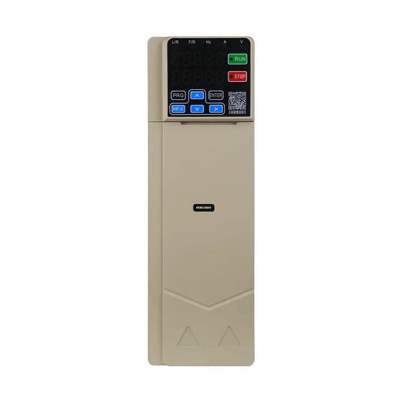
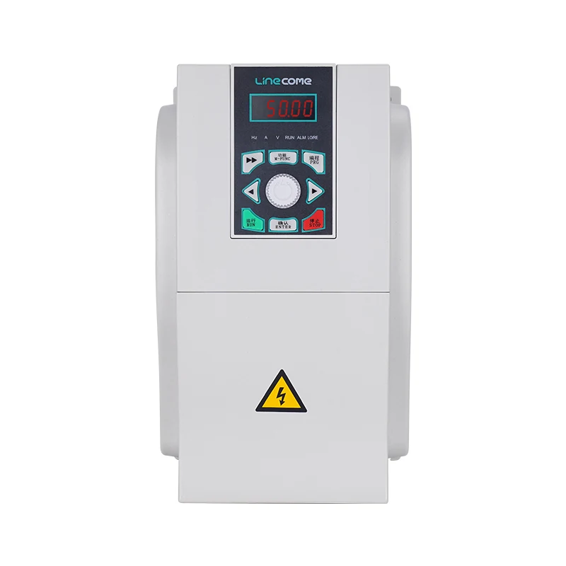
A LNC610 general-purpose VFD is a starting point for a model-specific enquiry. Request the instructions for the exact supplied drive and application before specifying an output contactor. The photograph, power range or family description does not establish a permitted switching sequence, relay function or bypass arrangement.
Define why the output contactor exists
Write a short functional statement: motor selection, part of an engineered bypass assembly, an operational disconnection function or another explicitly approved purpose. If the only explanation is “we always fit one,” the design review is incomplete. The selected device needs a reason that can be traced to the actual system requirements.
Do not turn an operational disconnection function into a claim of safe maintenance isolation. Whether equipment is suitable for isolation depends on its construction, markings, applicable requirements and the site’s energy-control procedure. Other electrical sources and mechanical energy may remain present. A contactor command or an auxiliary contact is not, by itself, verification of a safe condition for service.
The CCOHS lockout guidance explains the separate task of controlling hazardous energy. Use it as general safety context alongside local rules and the equipment instructions. This article addresses operational sequence review; it does not provide a complete safety circuit or an energized-work procedure.
Obtain the drive’s switching conditions before choosing timers
Ask the drive supplier what must be true before the contactor may open and before it may close. Those conditions may involve a documented output-disabled state, motor condition, permitted delay or a specific control option. Use the actual manual and supplier confirmation rather than adopting a sequence from another brand.
A zero frequency reference describes a requested command. It does not prove that the drive’s output stage has ceased switching or that a moving motor has no electrical effect. Similarly, a PLC stop bit does not prove that a stop has finished. The approved design must identify the actual status used to permit switching and explain its limitations.
If an existing control drawing opens the contactor immediately whenever the run command disappears, review it against the supplied drive instructions before treating it as correct. Avoid a universal delay value. The required behavior depends on the drive, stopping mode, motor and application, including what the system must do under an abnormal condition.
Review commands and feedback as separate signals
A command tells the contactor coil what the controller wants. Feedback reports a defined observed state. They should not be treated as the same evidence. The drawing must identify the feedback contact, its relationship to the power contacts and the diagnostic assumptions used by the controller.
For a normal closing request, the sequence should establish all required permissions before the request, then verify the expected feedback before allowing the drive to energize the selected path. For an opening request, the sequence must first achieve the documented switching condition. These are review principles, not a universal wiring diagram; the exact implementation requires engineering approval.
If feedback does not agree with the command, define the response and recovery path. Do not let the program continue merely because a timer expired. A timeout can detect that expected feedback failed to arrive; it cannot make an unverified contact position acceptable. Consider a missing signal, a stuck indication and a discrepancy that appears during operation separately.
RealPars’ interlock explanation distinguishes mechanical, electrical and logical prevention methods. Its general teaching helps describe the control architecture, but it does not certify an ordinary PLC sequence as a safety function or establish a required reliability level for this application.
Use a sequence-review table instead of a generic delay recipe
The following is an original design-review checklist. Apply it with the exact drive instructions, the approved power drawing and the interlock principles described above. It intentionally gives no contactor part number, fixed switching delay or universal safety rating.
| Sequence point | Evidence the reviewer needs | Condition that requires resolution |
|---|---|---|
| Initial state | Defined drive and contactor indications | Unknown position or inconsistent feedback |
| Connection request | Supplier-approved switching permission | Output state not established |
| Contactor closure | Feedback defined in the approved drawing | Command and feedback do not agree |
| Drive enable | Correct motor path and all required permissives | Missing or conflicting path confirmation |
| Normal stop | Documented stopping behavior | Opening requested before the permitted condition |
| Disconnection | Approved output state and contactor response | Feedback fails to reach the expected state |
| Abnormal event | Risk-assessed response for each initiating event | Ordinary stop logic assumed to cover every fault |
| Recovery | Reset conditions and a deliberate restart policy | Unexpected restart after a fault or power return |
Include who owns each acceptance decision. The drive supplier can define a permitted operating condition; the machine designer must integrate that information with the process and safety requirements. A component supplier’s statement does not validate the entire installed assembly.
Keep normal stopping and abnormal response distinct
A normal production stop may allow a controlled deceleration before a later disconnection. An emergency or fault can impose different priorities. Do not apply the normal-stop timing blindly to every abnormal event, or delay a required protective response merely to preserve a preferred switching sequence.
Have the responsible designer define the behavior for loss of control power, drive fault, contactor feedback disagreement and a competing motor-selection request. State which events inhibit restart and which require investigation. If the drive documentation and safety requirements appear to conflict, obtain an engineered resolution before operating the system.
The site’s emergency-stop reset guide is relevant to recovery: restoring a permissive should not create an unexpected restart. It complements this contactor review, but it does not prove that a particular stop category, safety function or isolation arrangement has been achieved.
Select the device for the actual electrical duty
Give the contactor supplier the drive and motor identities, operating voltage, continuous current, switching purpose, expected operating frequency and the approved sequence. Include the panel environment and the required coil supply. Do not select only from the motor’s power rating or assume that an input-side device can automatically be used on the output side.
Ask for confirmation of the relevant utilization and compatibility requirements for the specific duty. The engineering package must also consider any output accessories, motor branches and bypass connections. A single contactor data sheet does not validate a complete assembly or replace the drive’s instructions.
Where an output reactor or filter is present, show its position on the drawing and request a review of the entire arrangement. The long motor cable guide addresses cable-related output effects; those effects are a separate question from permission to switch a contactor. Solving one does not demonstrate that the other has been resolved.
Test the sequence without creating a destructive demonstration
Begin with drawing review and approved checks of the control logic before a powered motor test. Verify signal identity and expected state transitions through the authorized commissioning procedure. Do not deliberately open a loaded output path to prove that an interlock is necessary.
Prepare a test record with command, permitted-output-state indication, contactor feedback and drive status on a common timeline. State the timing resolution and what each signal actually proves. A slow screen refresh may hide the order of short transitions, so a visual observation of two indicator lamps is not always sufficient acceptance evidence.
Test normal requests, rejected requests and the approved simulated failure cases where the procedure permits them. Include local and remote control modes and restoration after control-power loss if those are part of the design. Remove temporary forces, jumpers and test arrangements before returning the machine to operation, and preserve the final configuration.
The VFD flying-start guide covers a different operating condition: a motor that is already moving when control resumes. If a selection or reconnection scheme can encounter a coasting motor, obtain a coordinated review. Do not assume that enabling a flying-start feature authorizes connecting that motor to an already active drive output.
Make the purchase and handover record specific
The final package should contain the exact drive manual, accepted switching conditions, contactor selection evidence, power and control drawings, feedback definitions, approved test results and recovery instructions. Record any unresolved restriction clearly, such as a prohibited operating mode or a required supplier confirmation before commissioning.
For a retrofit, document what changed from the previous system and update labels and operator instructions accordingly. A selector switch that once operated a direct-on-line circuit may have a different meaning after a VFD conversion. The handover should describe what the operator may request and what the controller must verify before the request is carried out.
Educational video: understand interlocking
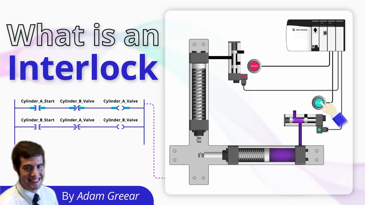
Video by RealPars. Watch What is an Interlock? on YouTube.
RealPars explains interlocking methods. Use this introduction to discuss why permission, command and feedback are different parts of a sequence. It is background education and does not provide the approved output-contactor circuit or timing for a LINECOME drive.
Frequently asked questions
Can I use the output contactor for routine start-stop control?
Do not make that the default arrangement while the drive is supplying the motor. Use the drive’s intended control commands and obtain model-specific approval for any output switching required by the application.
Does zero hertz on the display prove the contactor may switch?
No. Identify whether the display shows a reference or an actual operating value, then follow the drive’s documented switching conditions. A single display reading does not establish output isolation or a safe maintenance condition.
Does contactor feedback replace energy isolation for maintenance?
No. Feedback supports the defined operational sequence. Maintenance requires the applicable energy-control procedure, suitable isolation arrangements and verification of the safe condition by authorized personnel.


