




VFD acceleration and deceleration time settings define how quickly the drive changes its commanded output frequency, but the motor’s actual response also depends on available torque, load inertia, current limits and braking capacity. Begin with the machine’s required motion and the exact drive manual, then select a conservative ramp and verify the loaded response. A shorter setting is not automatically a better setting. Acceleration that exceeds available torque can trigger current limiting; deceleration that returns energy faster than the drive can handle can raise DC-link voltage.
This article focuses on choosing and validating ramp settings. For the wider mechanism, read how a variable frequency drive works. For resistor calculations, use the separate VFD braking resistor sizing guide; ramp settings cannot establish a resistor’s electrical or thermal rating.
First establish what the ramp parameter actually measures
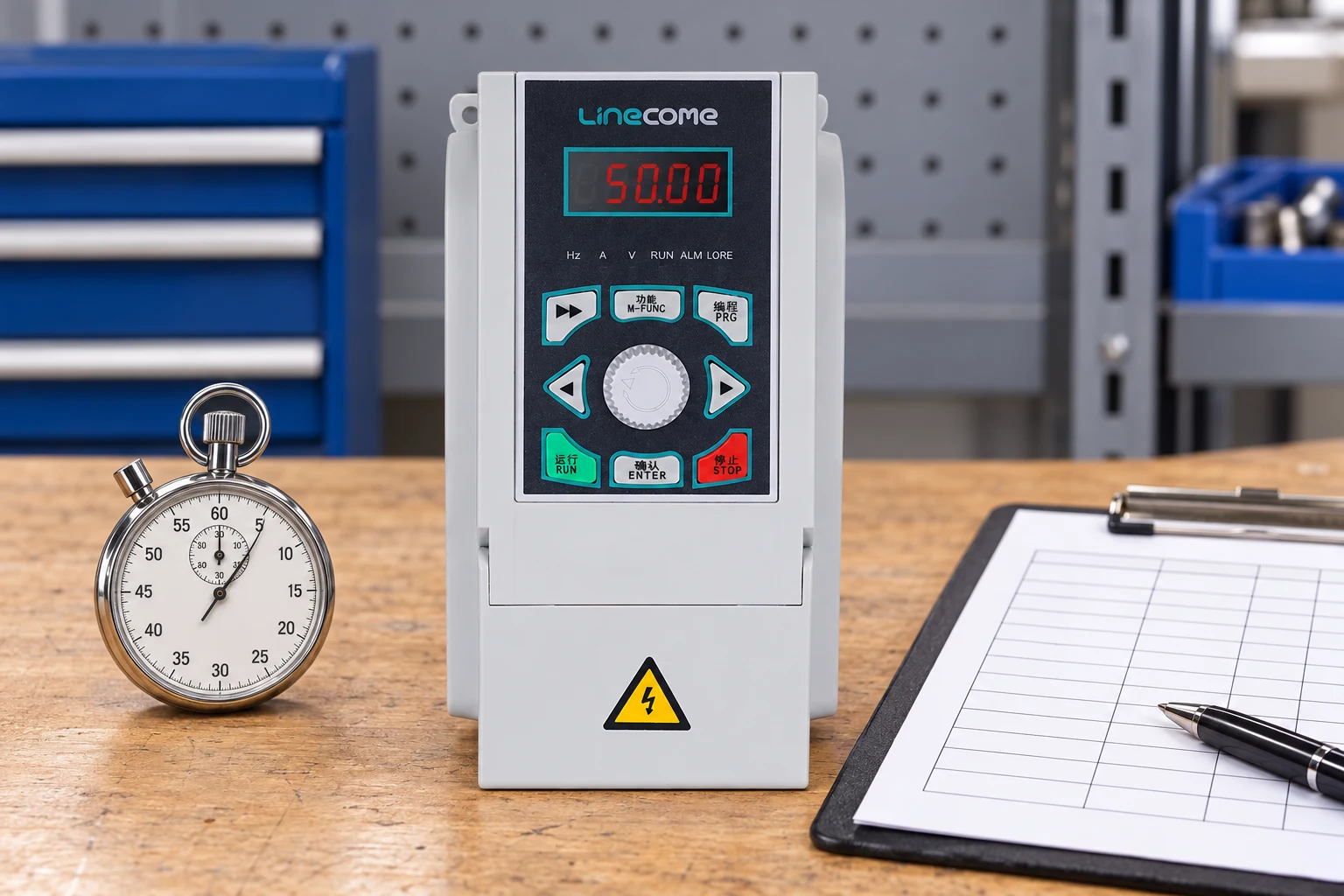
Two drives displaying the same acceleration time can produce different frequency changes because their manuals define the reference interval differently. One parameter may describe zero to maximum frequency; another may describe zero to a specified base frequency. Separate ramp groups, jog modes, process control and alternative stop modes can also affect which setting is active. Record the definition and selected control mode before making comparisons.
If a linear ramp is defined as zero to 50 Hz in ten seconds, the nominal frequency-change rate is 5 Hz per second. A change from 20 to 40 Hz would then take four seconds while that slope is active. If the reference is zero to 100 Hz instead, a ten-second parameter implies a different slope. These are illustrative definitions, not parameter instructions for a LINECOME model.
Distinguish frequency command, shaft speed and process response
The frequency command is the controller’s requested output. Shaft speed is the motor’s mechanical response. Flow, pressure, hook travel or conveyor movement is the process response. They are related but should not be treated as identical traces. An induction motor has slip; a drive may limit current; belts and couplings may introduce mechanical behavior that cannot be inferred from the displayed frequency alone.
During commissioning, record the commanded frequency and actual drive output together with motor current and the relevant process variable. Where shaft speed matters, obtain suitable speed feedback or measurement. A pressure surge appearing after a frequency change may reflect valve or piping behavior rather than an incorrect electrical ramp. Diagnosing the wrong trace can lead to repeated parameter changes without solving the cause.
Acceleration requires torque beyond the steady running load
A rotating system needs net accelerating torque to increase speed. In a simplified motor-shaft model, Tacc = J × Δω/t, where Tacc is accelerating torque in N·m, J is total inertia referred to the motor shaft in kg·m², Δω is angular-speed change in rad/s and t is time in seconds. Required motor torque also includes the load torque and relevant losses throughout the speed range.
This relationship follows the rotational dynamics explained by OpenStax’s rotational inertia chapter. A large fan, centrifuge or flywheel can demand substantial acceleration torque even when steady running power looks modest. Gearbox ratio and the location of each inertia must be handled consistently; do not combine load-shaft inertia with motor-shaft speed without conversion.
For an illustrative total inertia of 0.5 kg·m² and a speed change from zero to 1,500 rpm, angular-speed change is approximately 157.08 rad/s. A ten-second ramp requires about 7.85 N·m of net accelerating torque. A five-second ramp requires about 15.71 N·m. Both figures exclude the driven load’s resisting torque, so neither is a complete motor or drive selection.
Why the drive may not follow a very short acceleration setting
The drive’s current or torque limiter may intervene before the requested ramp completes. Depending on the control design, the drive may extend acceleration, reduce its frequency-change rate or trip. A five-second command followed by an eight-second actual acceleration is useful evidence about the system, not proof that the parameter failed to save.
Check motor nameplate entries, control mode, mechanical freedom and the application’s torque demand before increasing a limit. Confirm that overload capacity applies to the selected drive frame, ambient conditions and duty. Repeated short starts can create a thermal problem that a single successful start does not reveal. A larger current limit cannot compensate for a jammed mechanism or an unsuitable motor connection.
| Observation | Possible explanation | Useful verification |
|---|---|---|
| Current rises and ramp stretches | Available accelerating torque is limited | Compare current, speed and load through the complete start |
| Motor turns but process responds late | Mechanical or hydraulic delay | Check coupling, valve state, flow and pressure |
| Trips occur only after repeated starts | Thermal accumulation or changed duty | Review cycle frequency and motor/drive temperatures |
| DC voltage rises during stopping | Regenerated energy exceeds the available absorption path | Check stop mode, braking configuration and actual deceleration |
| Machine jerks at ramp boundaries | Abrupt acceleration change or mechanical backlash | Assess ramp shape and transmission behavior |
The table is a diagnostic checklist, not a list of guaranteed fault causes. Preserve the recorded fault code and operating conditions before resetting equipment. More than one cause can produce the same symptom.
Deceleration is an energy-management problem
When the load drives the motor during slowing, mechanical energy can return to the drive’s DC link. The energy released by a rotating system is related to its change in kinetic energy: ΔE = ½J(ω₁² − ω₂²). The OpenStax rotational dynamics discussion provides background on the torque that changes rotational motion.
A longer stop can reduce average braking power, but it does not remove the original energy. The path for that energy depends on losses, braking hardware and drive architecture. A suitable resistor and chopper dissipate it as heat; an appropriate regenerative system can return energy to the supply. Some drives alter the ramp to avoid overvoltage. Confirm the actual stopping behavior rather than assuming the entered number is guaranteed.
Vertical motion adds another consideration: lowering may produce regenerative energy throughout travel. Do not shorten a hoist ramp based only on an unloaded trial. Mechanical holding, brake coordination and fault response remain machine-level requirements. The drive’s ordinary stop command is not evidence that a suspended load will remain secure after power loss.
Choose a ramp shape for the mechanical system
A linear frequency ramp changes frequency at an approximately constant rate between its endpoints. At the boundaries, acceleration can change abruptly. An S-shaped profile smooths the transition into and out of acceleration, which may help reduce mechanical shock in suitable applications. Its actual definition, timing and available adjustment depend on the drive.
Do not assume that adding an S-curve preserves the original total travel time. Some controls include smoothing within the programmed duration, while others alter the effective transition. Verify the actual speed-time curve and the machine’s permitted movement. Avoid making the smoothest-looking trace the only acceptance criterion: the process must still reach its required operating point within an acceptable time.
For pumps, validate the hydraulic response as well
A pump’s acceptable start and stop sequence depends on the piping system, valves, static head, minimum flow and other operating constraints. A generic “ten seconds for every pump” rule ignores those differences. A smooth motor ramp can still produce an undesirable pressure event if a check valve closes unexpectedly or the process changes rapidly.
The DOE’s variable-speed pumping guide supports evaluating the pump and system together. Use pressure and flow records to validate proposed sequences. For a centrifugal pump in a friction-dominated system, changing speed changes the operating point; where static head is significant, the response can be different. Stop testing if process limits are exceeded.
A practical commissioning sequence
First agree the mechanical and process limits with the machine owner. Identify permitted speed range, starting conditions, load, required stop time and what happens after a fault or power interruption. Confirm that the electrical installation and protective measures are ready using the VFD installation checklist. Ramp tuning should not be used to work around unresolved installation defects.
Next record the original settings, including the active ramp group and stop mode. Begin with the supplier-approved starting values and a controlled test condition. Change one factor at a time and log the result. Move from initial checks to representative load conditions under the agreed commissioning plan. Include the shortest expected production cycle, not only a single cold start.
Finally compare the requested and actual timing. Confirm that current, thermal behavior, DC voltage where available, mechanical motion and process response remain acceptable. Document the final configuration, test load and any limitations. A ramp verified with an empty conveyor or low water demand should not silently become an approval for the maximum production condition.
Information to include in a drive enquiry
Send motor nameplate data, supply voltage, load type, maximum inertia or an engineering estimate, required speed range, starting load, stopping requirements and cycles per hour. Include the proposed control architecture and whether the equipment may overhaul the motor. Ask the supplier to identify which ramp parameters and limits apply to the quoted hardware and software.
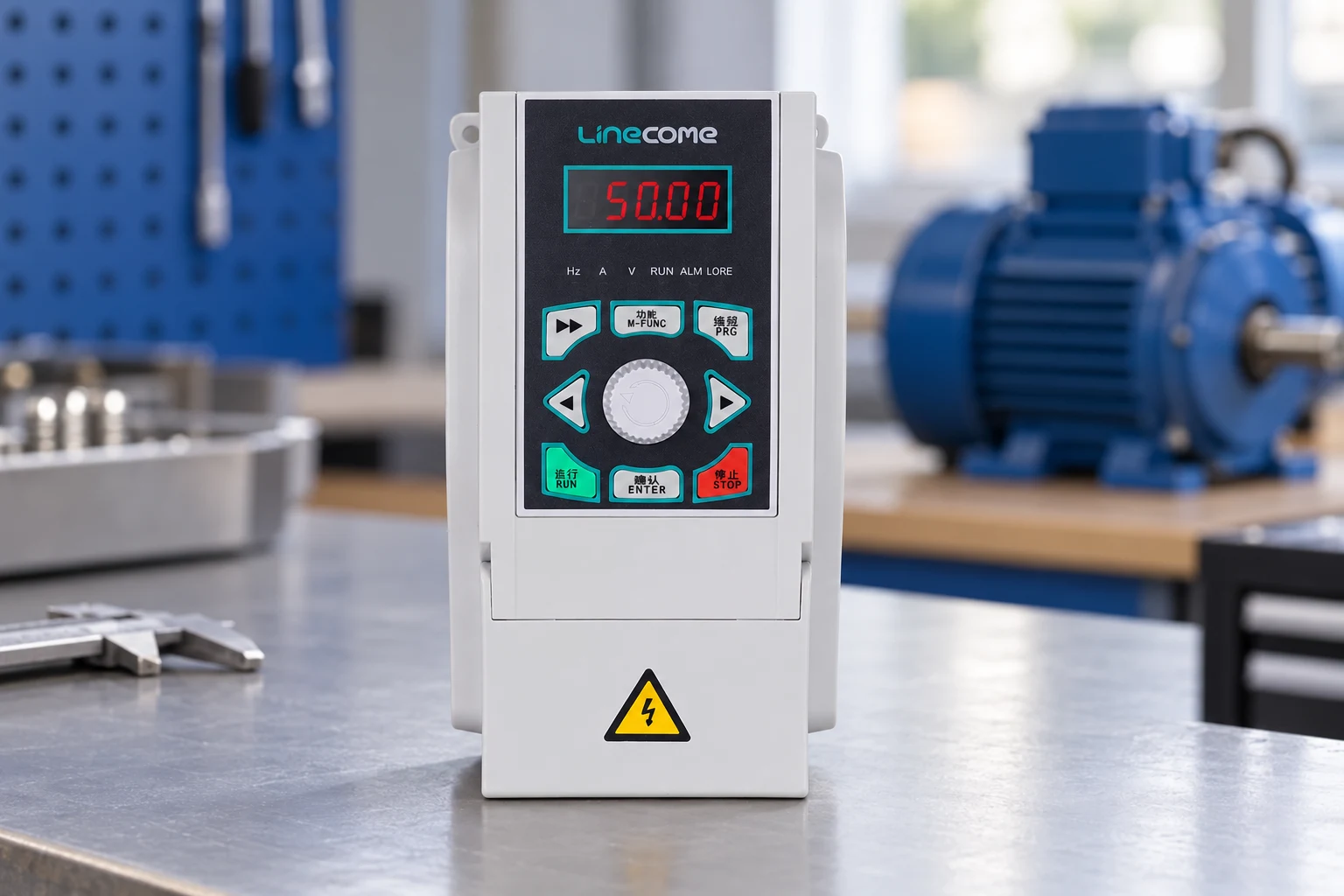
Explore the LINECOME LNC820 range for a model discussion, or compare families through the product hub. A product photograph illustrates the drive enclosure; it does not establish stopping performance, braking options or approval for a particular application. Require confirmation for the exact model before ordering.
Further learning
The Engineering Mindset’s independent explanation of the rectifier, DC link and inverter provides useful background to the command and energy paths discussed here. It does not replace the installed drive manual or the machine’s commissioning procedure.
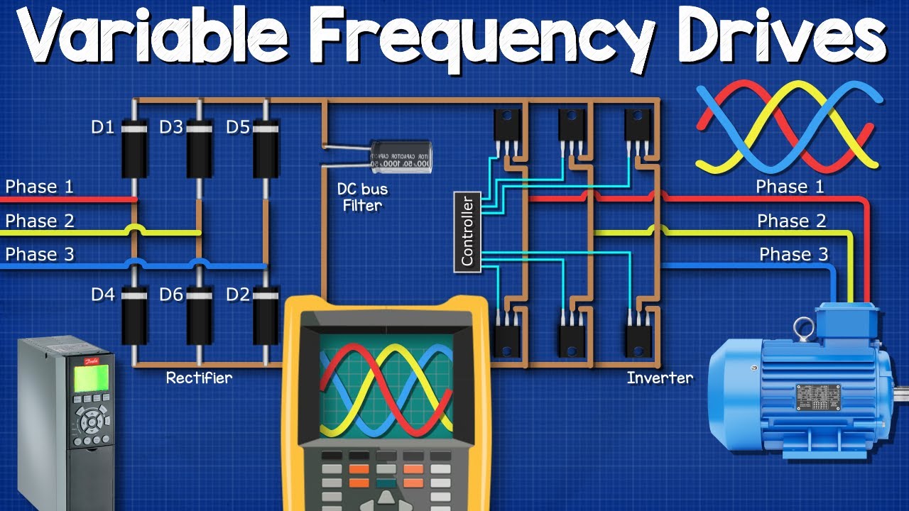
Watch the VFD explanation on YouTube.
Frequently asked questions
Is the entered ramp time the guaranteed stopping time?
No. Stop mode, load, limits and braking capacity can change the actual response. Measure stopping behavior under the required operating conditions.
Should acceleration and deceleration use the same time?
Not necessarily. Available motoring torque and the ability to absorb regenerated energy are different constraints. Validate each direction separately.
Can a longer ramp fix every overcurrent trip?
No. It may reduce acceleration demand, but mechanical faults, incorrect motor data and electrical problems still need diagnosis.
Does an S-curve remove the need for braking hardware?
No. It changes the motion profile. The energy returned by the load still requires an appropriate path and suitable equipment ratings.


