




VFD carrier frequency is the switching rate used to synthesize the motor-output waveform; it is different from the output frequency that principally determines motor speed. Changing it can affect audible sound, drive losses and the motor/cable system. The correct setting is the one permitted by the exact drive manual and validated for the installation. A quieter motor is not sufficient proof of a successful change. Check output-current capability, enclosure temperature, motor behavior and cable/filter restrictions before retaining a new setting.
This article focuses on choosing and verifying a switching-frequency setting. It complements our VFD operating-principle guide and our low-speed motor overheating guide. Our low- and high-frequency efficiency comparison covers the broader efficiency distinction; this page owns the setting-verification workflow. It does not recommend a universal kilohertz value or claim that every LINECOME model provides the same carrier-frequency options.
Separate carrier frequency from motor-output frequency
A drive may command a motor-output fundamental of 50 Hz while switching its power devices many times within each electrical cycle. The first quantity describes the motor’s commanded electrical frequency; the second describes how the drive builds the output waveform. Their units may both include hertz, but their functions are different.
Changing the carrier setting is therefore not the usual method for changing shaft speed. Speed commands, motor pole count, control mode and slip behavior belong to the motor-control discussion. A carrier adjustment instead changes part of the switching behavior, with consequences that depend on the power stage and connected system.
Parameter names vary between manufacturers. Some drives use selectable steps, a permitted range or automatic adjustment under certain conditions. Before interpreting a displayed number, confirm whether it is a fixed command, a maximum permitted value or an automatically managed setting. Save the current parameter backup and manual revision.
Why a higher setting may sound quieter
Switching-related forces in a motor can produce audible tones. Moving the switching pattern may alter the sound heard near the motor, and a higher carrier setting can reduce an objectionable tone in some installations. The result depends on the motor and operating point; it is not a guarantee of silence.
First identify the source of the noise. Bearings, loose panels, cooling fans, airflow and mechanical resonance can produce sounds that a carrier change will not correct. Record whether the sound follows motor speed, process load or the drive’s switching behavior. A recording can document a complaint, but it is not a calibrated noise measurement.
Also establish where noise matters. A tone acceptable inside an unattended machine room may be unacceptable beside an occupied workstation. If occupational exposure is a concern, use an appropriate assessment by competent personnel rather than selecting parameters solely by ear.
Understand the drive heating trade-off
Power-device switching creates losses. More switching events can increase the switching-loss component, so a high carrier setting may affect the drive’s thermal margin or permitted continuous output current. The size of that effect is model-specific and depends on operating current, voltage and cooling conditions.
Check the manufacturer’s current-rating or derating information for the selected carrier setting. Do not borrow a curve from a different frame size or product family. The relevant condition is the drive’s capability in its actual enclosure and environment, not the largest current number shown on a general sales page.
Enclosure ventilation and ambient temperature matter at the same time. A setting accepted during a brief open-door test may be unsuitable during normal closed-door production. Verify the installation in its intended operating condition and preserve required clearances. Do not bypass a fan or thermal warning to maintain a preferred acoustic result.
Use a decision table before changing the parameter
This table organizes a review without inventing numerical limits. The exact drive, motor and accessory manuals determine what is allowed. Record the applicable manual page beside each decision so another engineer can reproduce the selection.
| Observed concern | Check before adjustment | Evidence required afterward |
|---|---|---|
| Audible electrical tone | Confirm source and permitted switching settings | Sound observation at representative speed and load |
| Drive runs hot | Cooling, ambient conditions and current derating | Thermal indications during accepted duty |
| Long motor cable | Cable limits and approved output accessories | Manufacturer compatibility confirmation |
| Motor temperature concern | Load, cooling, motor suitability and waveform effects | Accepted motor thermal assessment |
| Interference complaint | Earthing, shielding and installation arrangement | Repeatable symptom checks and appropriate measurements |
Review the motor and cable as a system
A motor drive does not operate independently of its output cable and motor. Switching edges, cable characteristics and motor insulation form an interacting system. Carrier frequency is one part of that system; it does not alone describe voltage rise time or settle every reflected-wave concern.
The Department of Energy’s motor and adjustable-speed-drive interaction guide provides background on motor compatibility and output-side concerns. Use that context to ask better questions about your installation. It does not establish the allowable cable length or filter requirement for a particular LINECOME unit.
Provide the supplier with actual cable length, cable construction, motor data and any output reactor or filter model. Ask whether the proposed carrier setting is supported with that combination. If the cable route changes during a retrofit, revisit the assessment rather than carrying an old approval forward automatically.
Do not use switching frequency as a universal overheating cure
Motor temperature depends on load, speed, cooling, electrical supply characteristics and operating duty. A self-ventilated motor may have reduced cooling at low shaft speed even when its current appears ordinary. Raising the carrier frequency does not restore missing mechanical airflow.
Likewise, lowering the setting does not make an overloaded mechanism acceptable. Compare the process demand with the motor’s permitted operating envelope. Check thermal sensor arrangements and the motor model configured in the drive. The protection system must reflect the motor and application, not merely a desire to avoid trips.
Distinguish drive temperature from motor temperature in the record. An adjustment can improve one observation while worsening another. Assess both under the same representative load and ambient conditions. If a measurement method changes between tests, document that change so the comparison is not misleading.
Investigate interference before treating the parameter as the cause
A drive installation can interact with nearby instrumentation through several paths. Poor cable segregation, unsuitable shielding termination, grounding arrangements and cable routing all deserve review. Changing a carrier setting may change a symptom without correcting an installation defect.
Record exactly what fails: a sensor reading, a communications link, a protective device or another specific function. Note whether the symptom follows start/stop events, speed or load. A general statement that the drive is “making electrical noise” is too broad to guide a reliable correction.
Use the approved installation manual and competent electrical support to evaluate the arrangement. Do not disconnect protective earth to test an interference theory. Any output accessory must be approved for the drive and application, including its thermal and switching-frequency conditions.
Run a controlled comparison
Begin with the documented baseline setting and a known operating condition. Save motor speed, process load, output current, drive thermal indication, motor thermal information and the reported symptom. Decide in advance which outcomes will justify retaining the change and which will require reverting it.
Change only an allowed parameter and keep other conditions as consistent as practical. Test the operating modes that matter: startup, steady production, low-speed work and repeated cycles where applicable. Do not judge a heat-related change solely during a short idle run.
For background on interpreting motor systems as complete applications, the Department of Energy motor-systems resources emphasize system-level assessment. The practical lesson here is to compare the complete operating result rather than one isolated sound or display value.
Document the accepted setting and its limits
The final record should identify the exact drive model, software version, carrier setting, continuous-current conditions, motor, cable and accessories. Include the test duty and ambient conditions. If the drive automatically modifies its switching behavior, describe that feature as documented rather than reporting a commanded number as a measured constant.
Write down why the setting was accepted. For example, the objectionable tone changed while the manufacturer-approved current capability remained adequate and the observed thermal behavior met the accepted criteria. This is stronger evidence than a note saying “increased frequency: better.” Preserve any remaining restriction on load or environment.
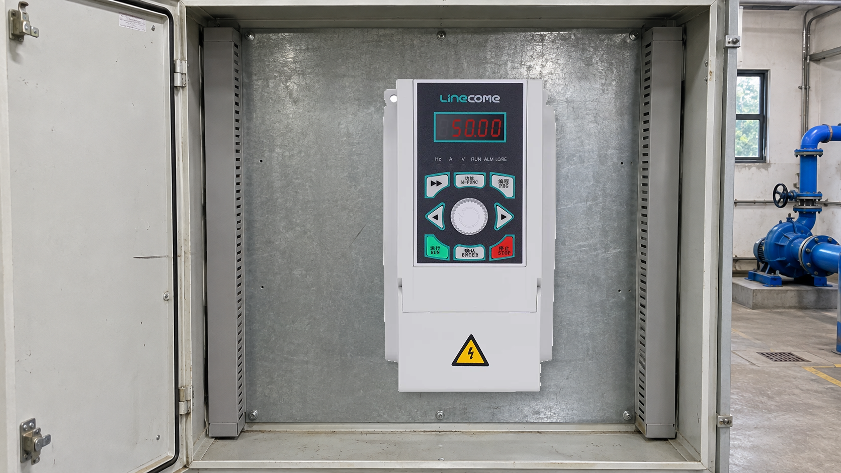
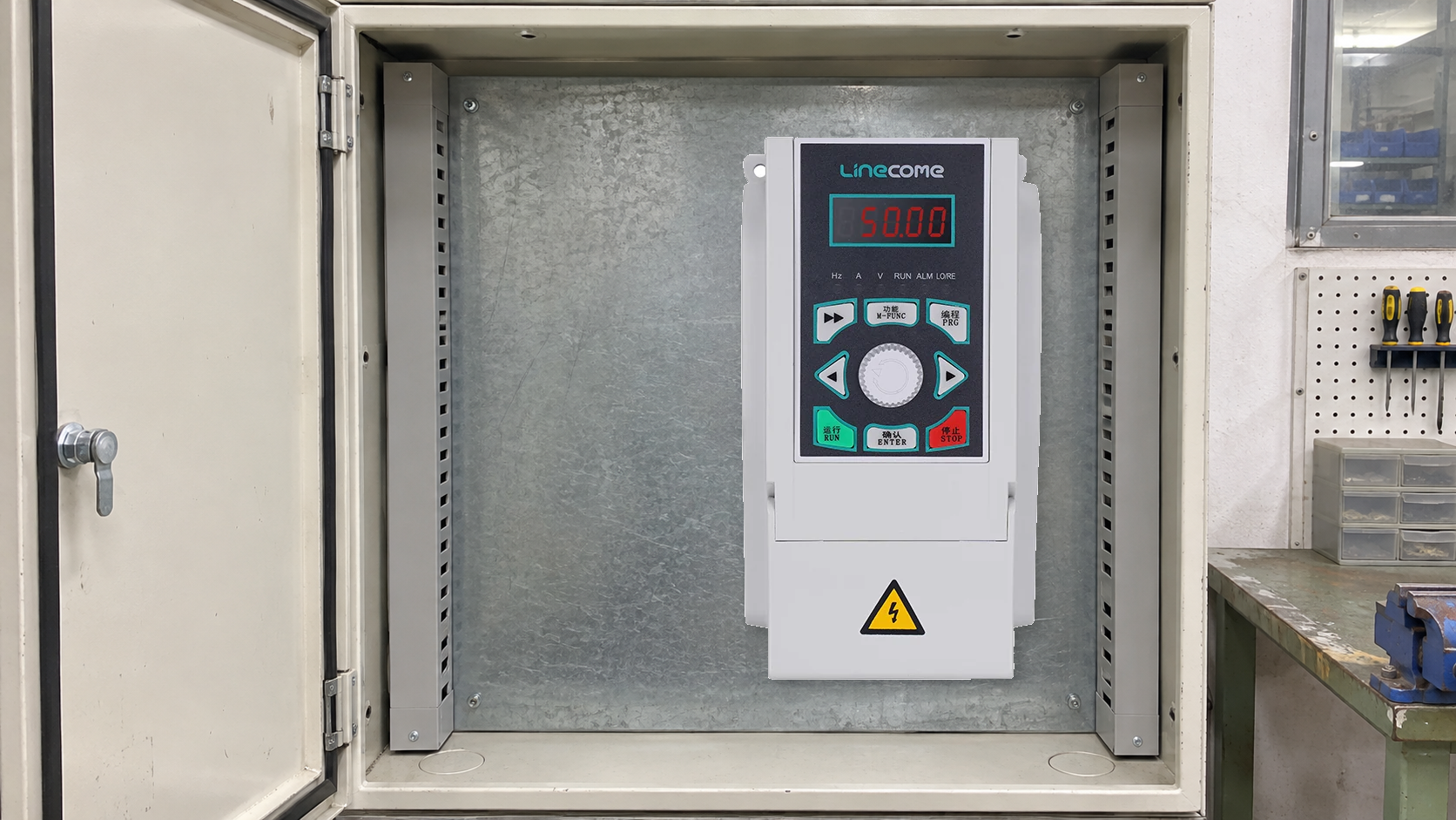
Request model-specific details through the LINECOME LNC820 product range. A product photograph does not identify the available switching options or prove a thermal rating. Supply the exact nameplate and installation information before asking for a recommended setting.
Work safely and manage later changes
Parameter review does not authorize live electrical work. Where inspection requires access to electrical parts, follow the applicable safe-work procedure and the equipment instructions. OSHA 1910.333 addresses electrical work practices for covered US workplaces, including deenergization and stored-energy concerns.
Reassess the setting if the motor, cable, filter, enclosure cooling or production duty changes. A quieter setting validated on a lightly loaded machine may need a new review after a capacity increase. Keep the accepted parameter file with the installation record so future maintenance can distinguish deliberate choices from accidental changes.
If the immediate problem is a current trip rather than audible sound, use the overcurrent fault investigation guide and the ramp-time commissioning guide to organize that separate investigation. Do not change carrier settings at random while an unexplained fault remains unresolved.
Further learning
The Engineering Mindset’s explanation introduces the switching-based motor-drive power stage. It helps distinguish the output fundamental from inverter switching, but it does not supply a universal parameter recommendation.
Frequently asked questions
Does carrier frequency set motor speed?
No. Carrier frequency describes inverter switching. The output fundamental and motor-control system govern the commanded motor-speed behavior.
Is the highest setting always best?
No. Acoustic results must be balanced with manufacturer restrictions, current capability, thermal conditions and the connected motor/cable system.
Can I use another drive’s derating curve?
No. Apply the documentation for the exact model and operating conditions. A different frame or product family may have different restrictions.
What should I verify after changing the setting?
Verify the original symptom, available current capability, drive and motor thermal behavior, process operation and any cable or accessory restrictions under representative duty.


